
FAIL of the day #1: Repair of NiMH charger

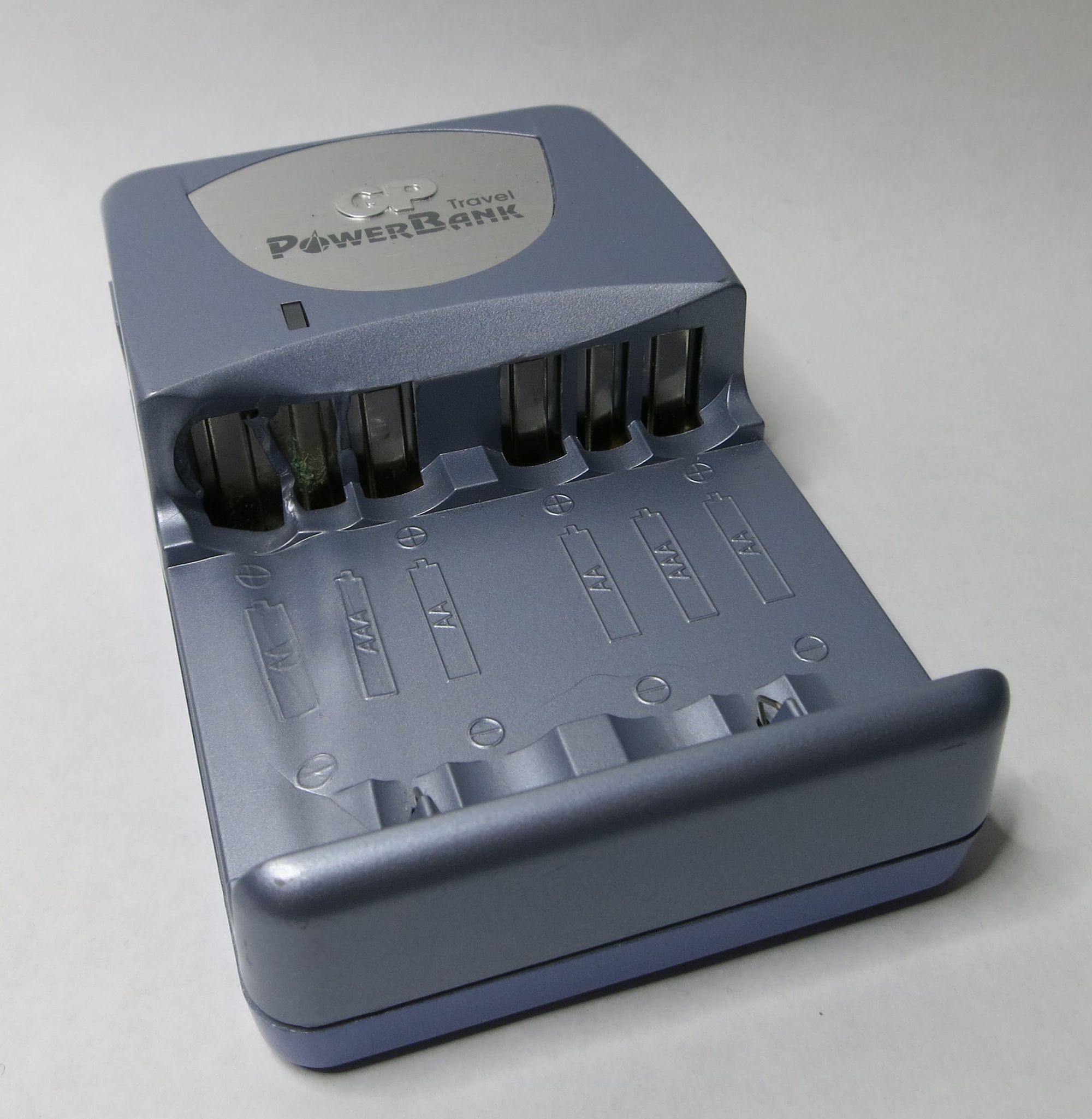
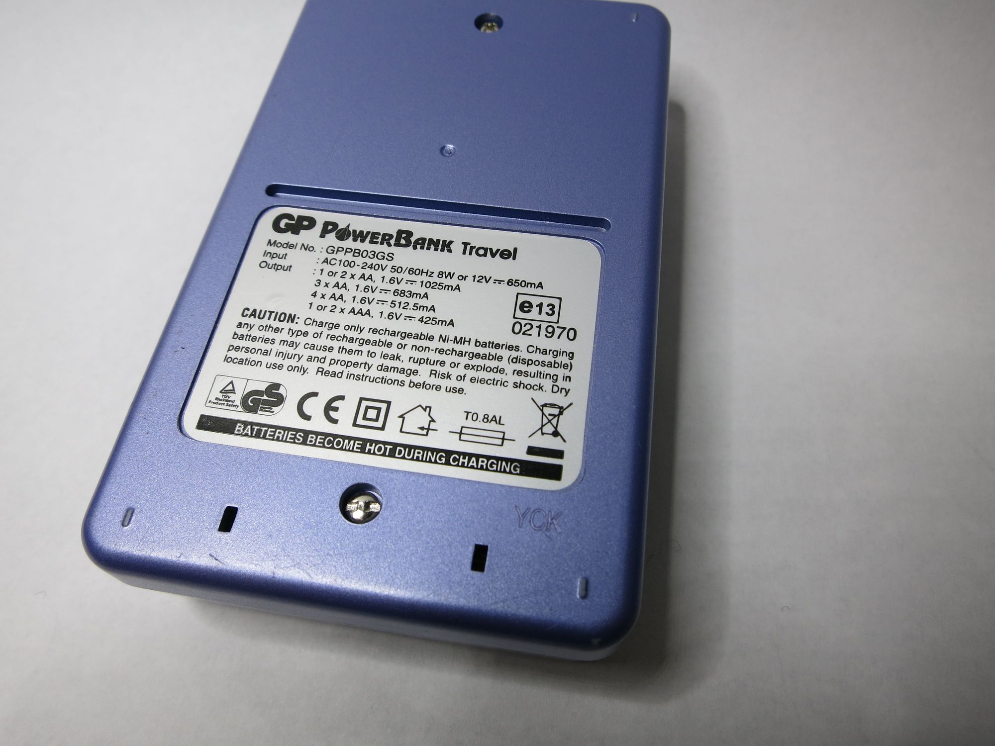
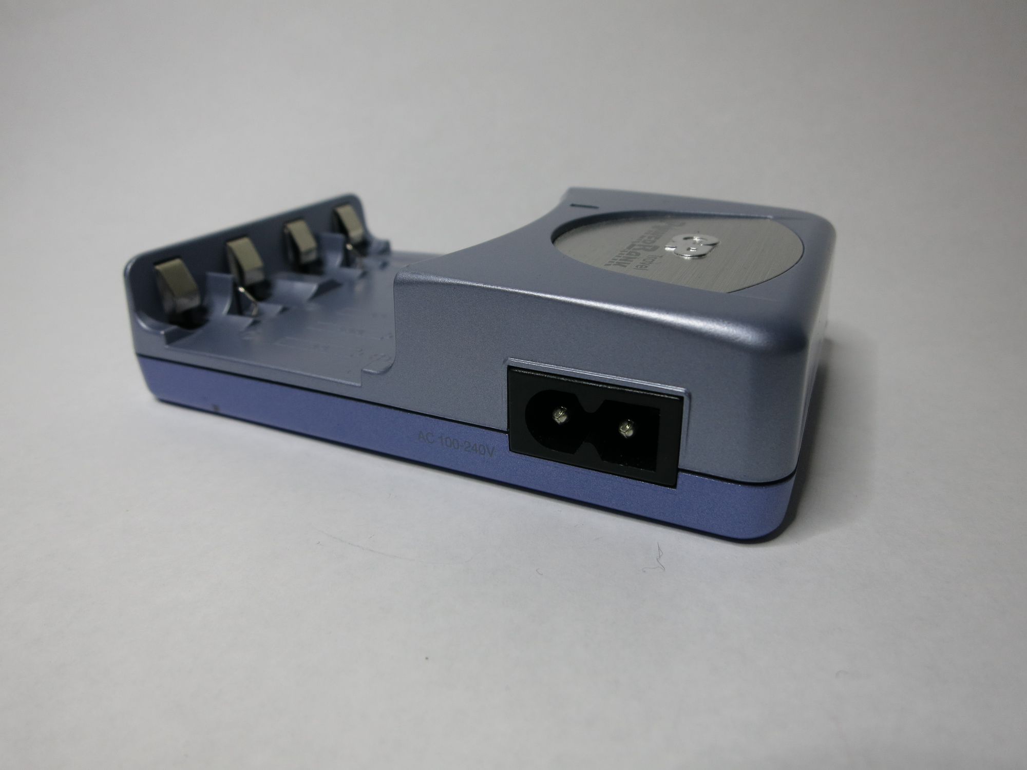
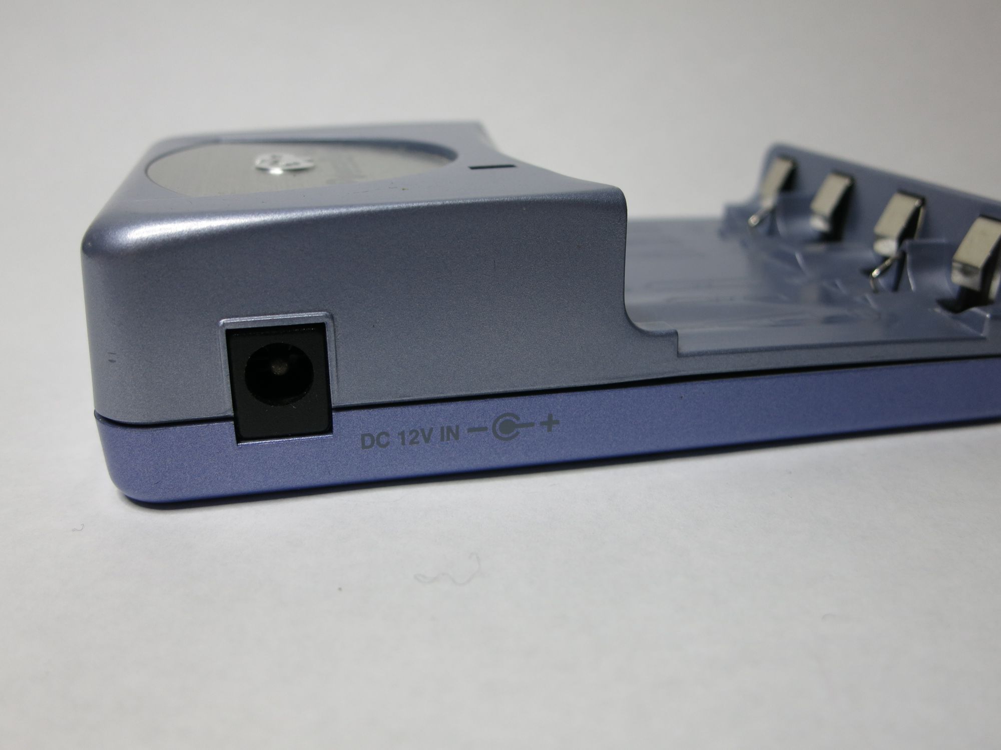
When buying some GP branded NiMH rechargeable batteries about a year ago, a “GP PowerBank Travel” charger (model GPPB03GS) was included as a promotion. It’s a nice little charger that runs both off 220 V and 12 V (for use in car, I presume). It can charge 1-4 AA batteries, or 1-2 AAA batteries, with additional trickle charging after full capacity has been reached.
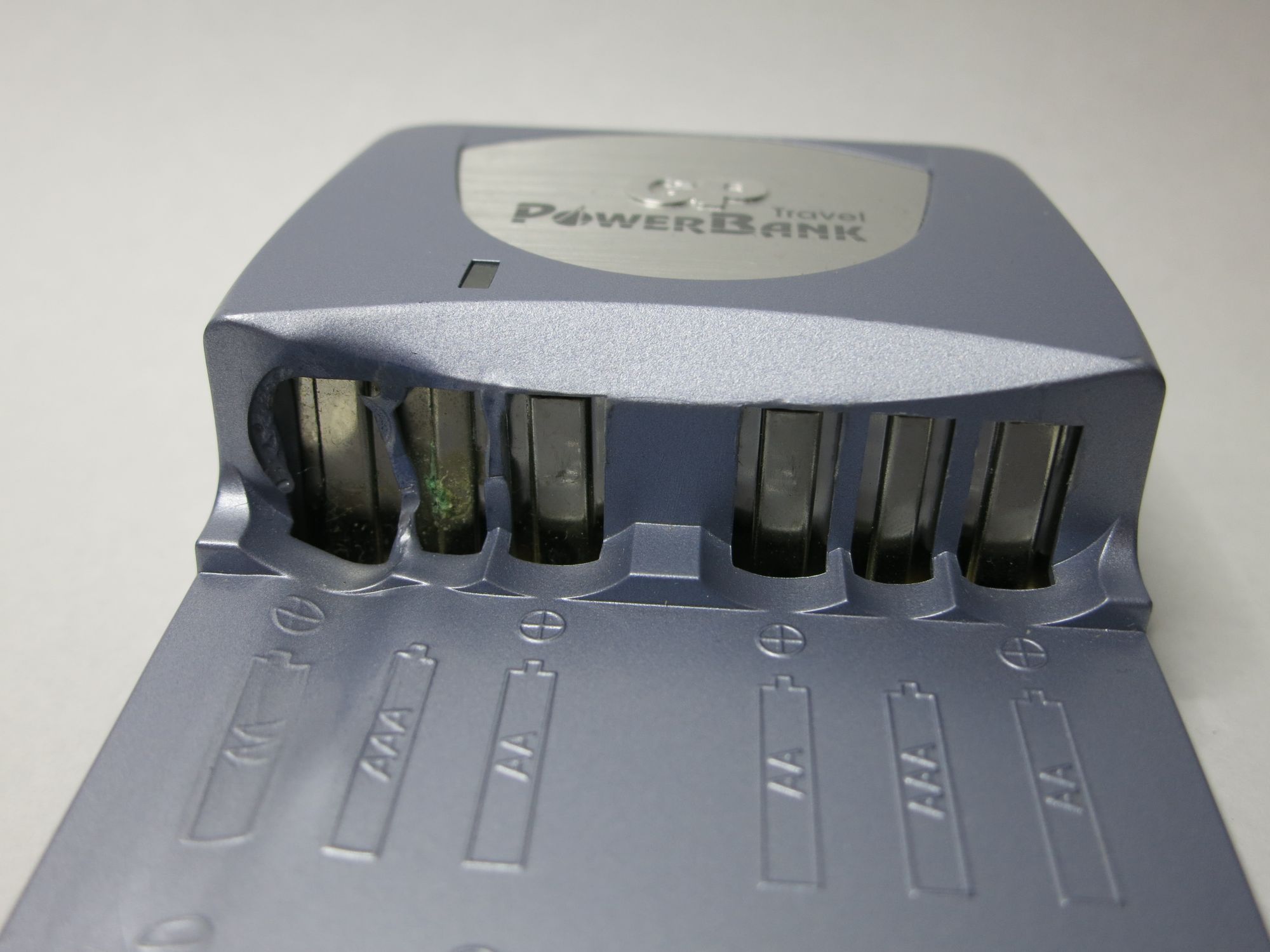
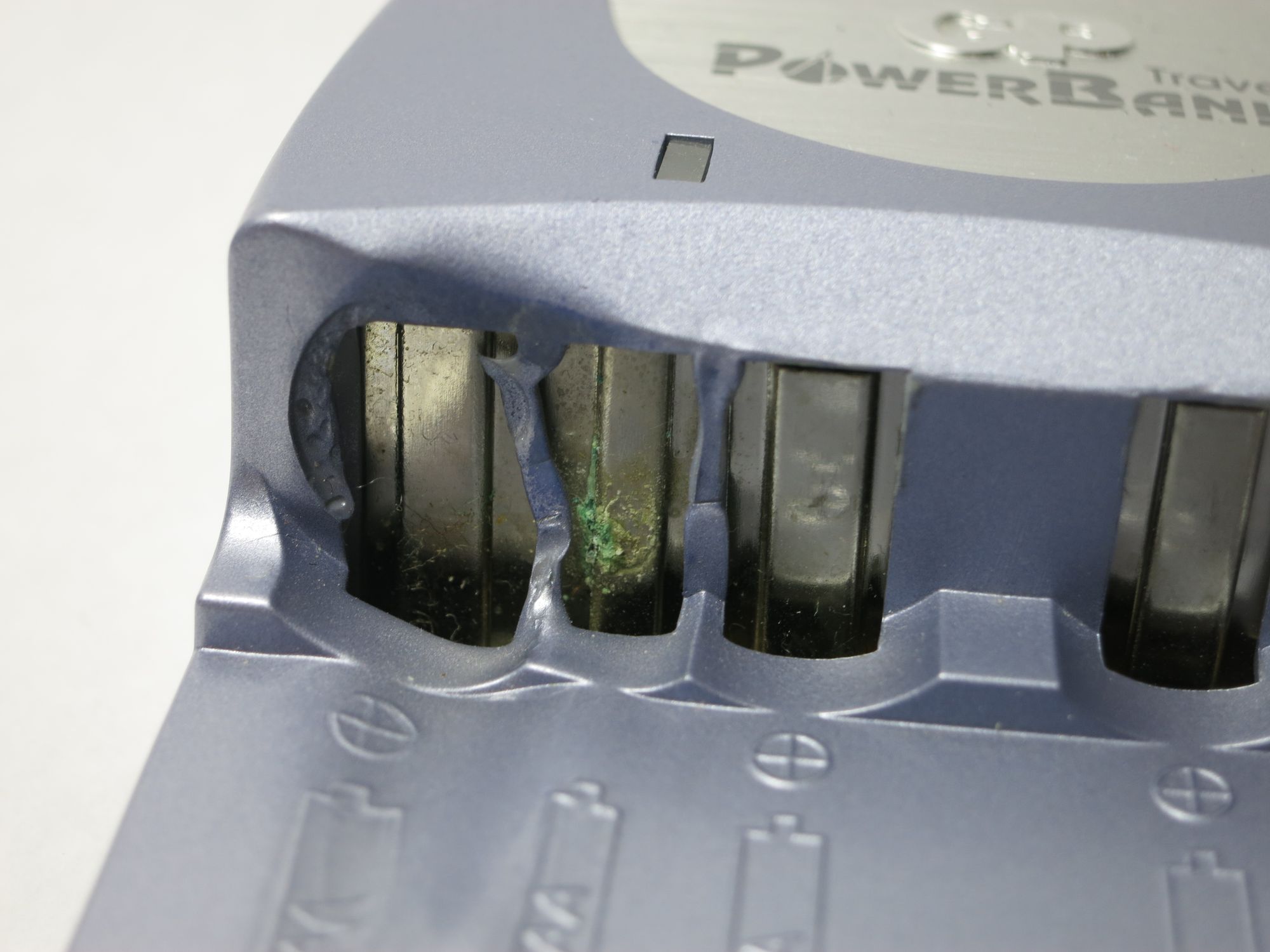
The charger worked well for some months, but one day after charging some batteries overnight the LED blinked red, and when removing the batteries it was clear something had gone wrong. See the melted plastic? Not good.
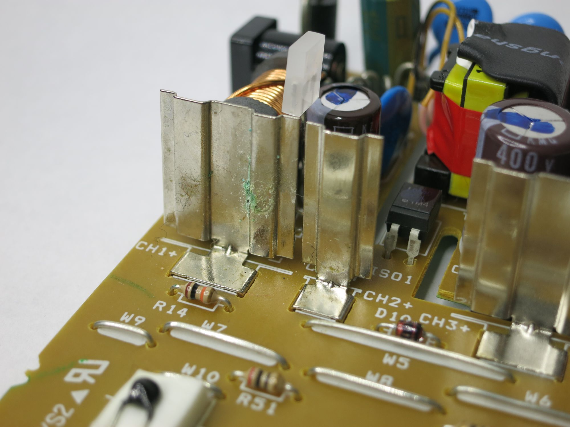
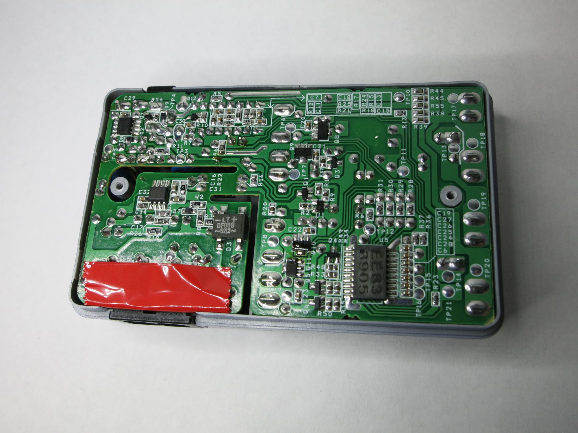
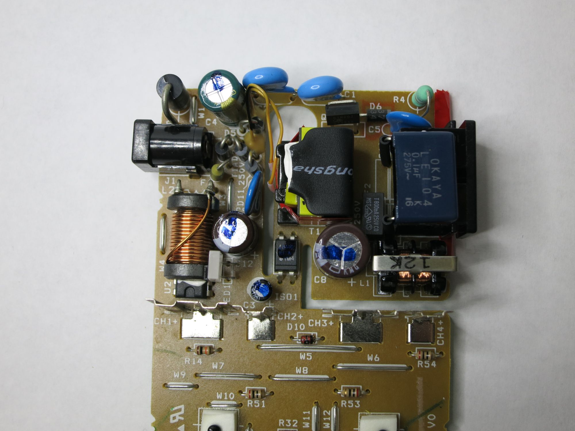
As this was very much an el-cheapo charger, one should probably not expect much from it. But I was still curious about how the 220V was brought down to more useful voltage levels, and if the internals would live up to safety standards. I was actually quite surprised at how complex and well designed the internals were:
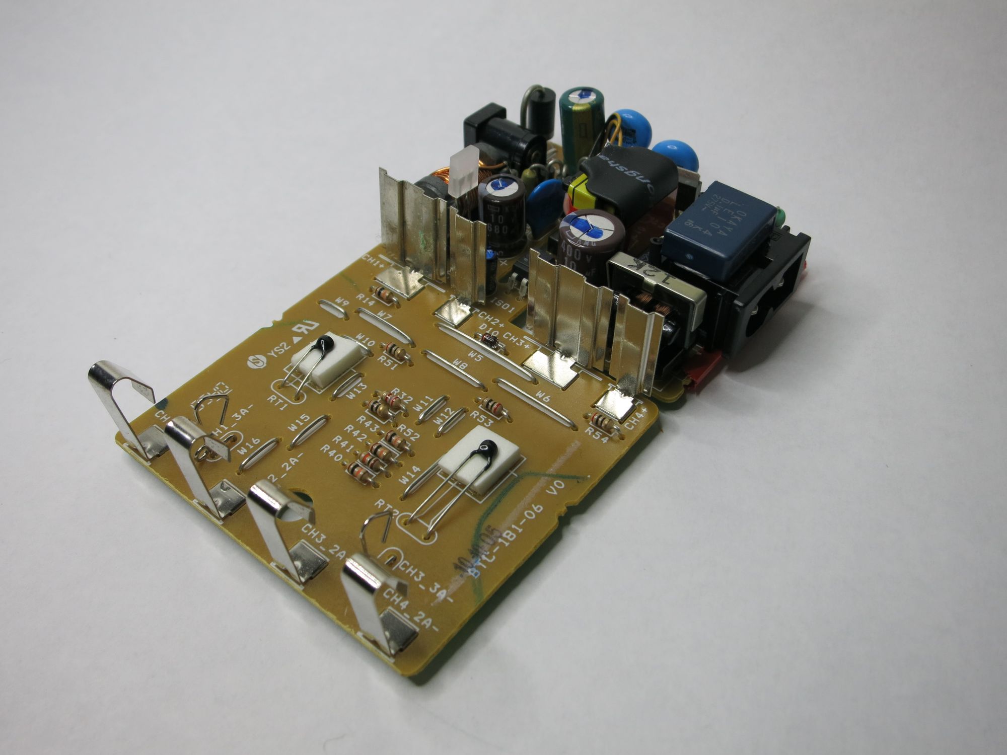
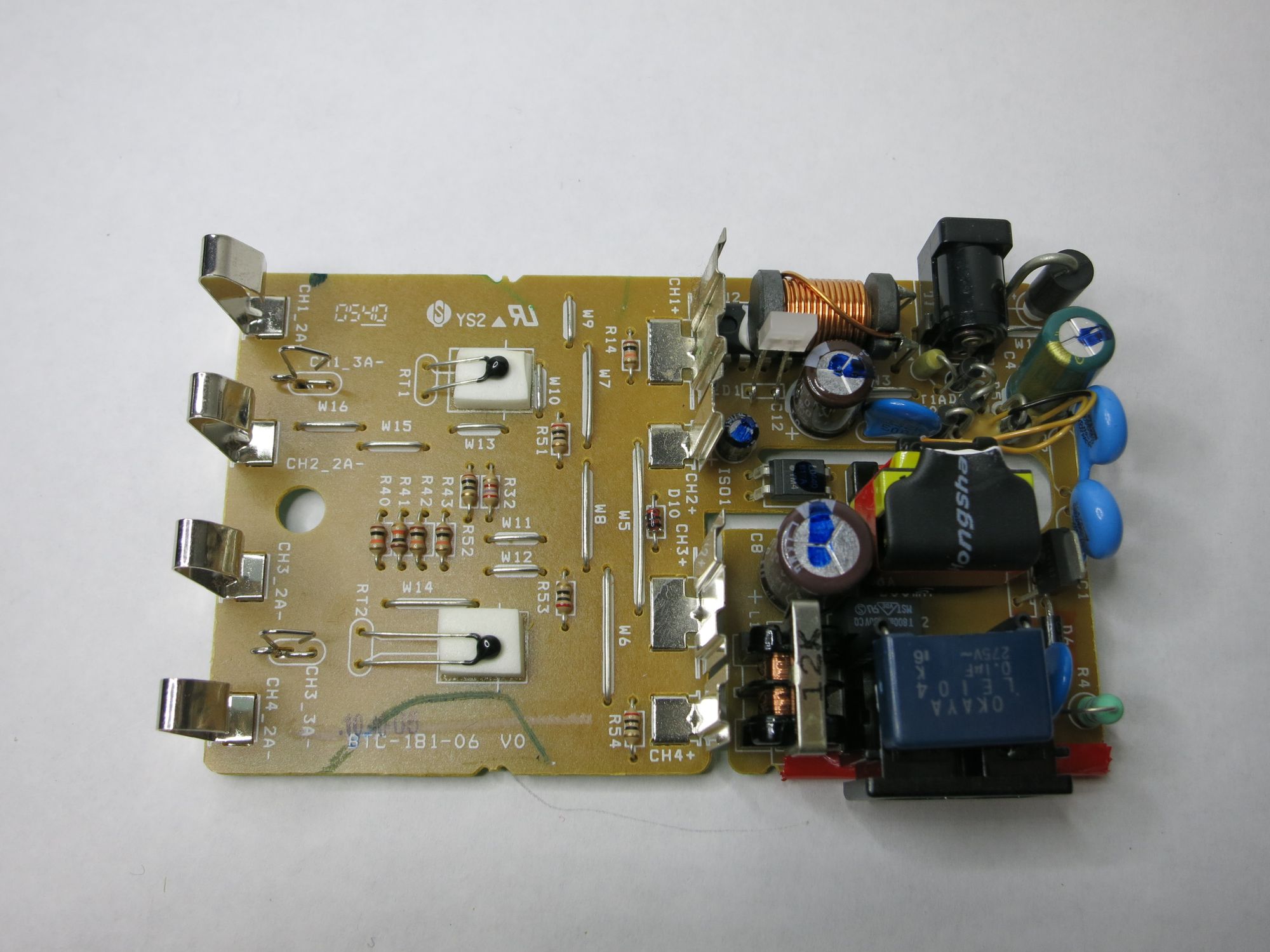
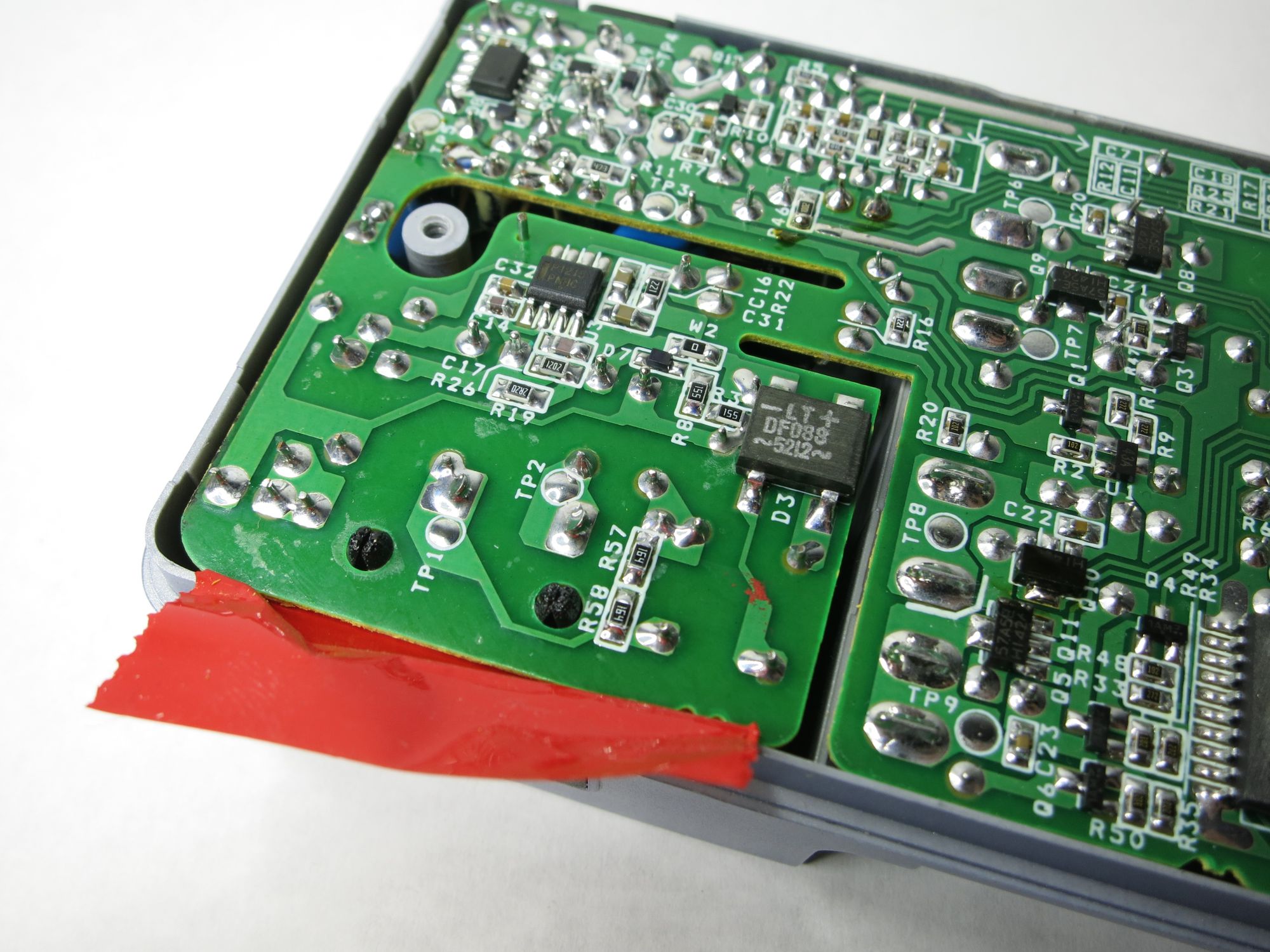
Looking closer, there are three distinct parts of the PCB:
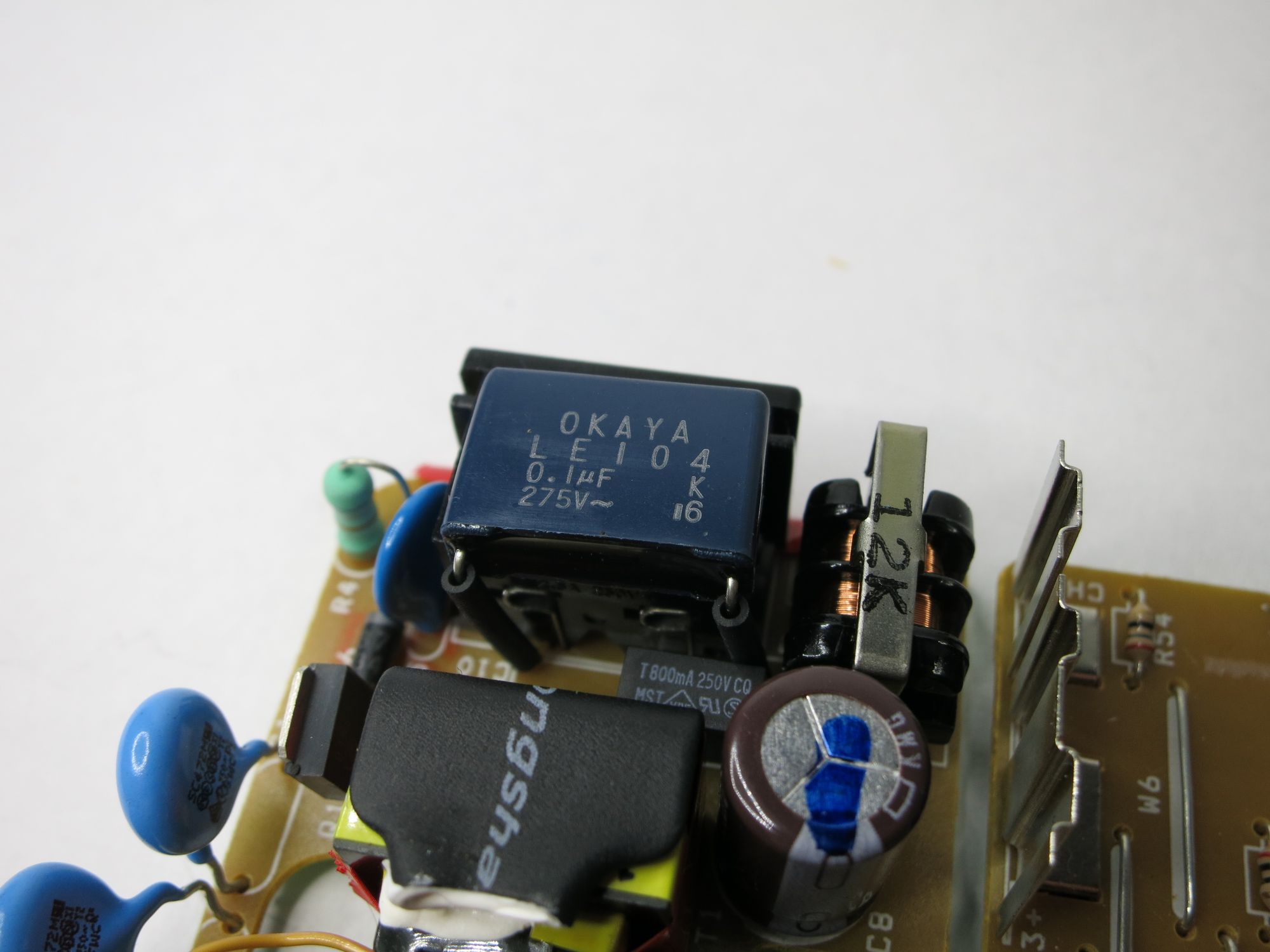
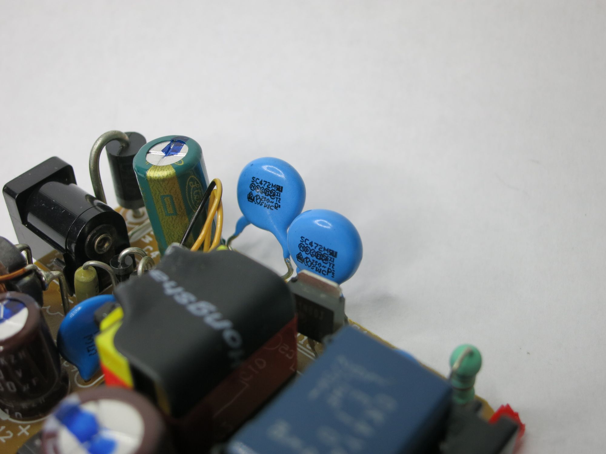
– 220V section, which is shielded with plastic blast shields towards rest of the electronics – nice! This is a classic Switched Mode Power Supply (=SMPS), with an optocoupler feedback loop. Looks like a SMD type TL431 voltage reference – very common in SMPS designs.
– 12V section, with some protection diodes, filter caps etc – but no other major components.
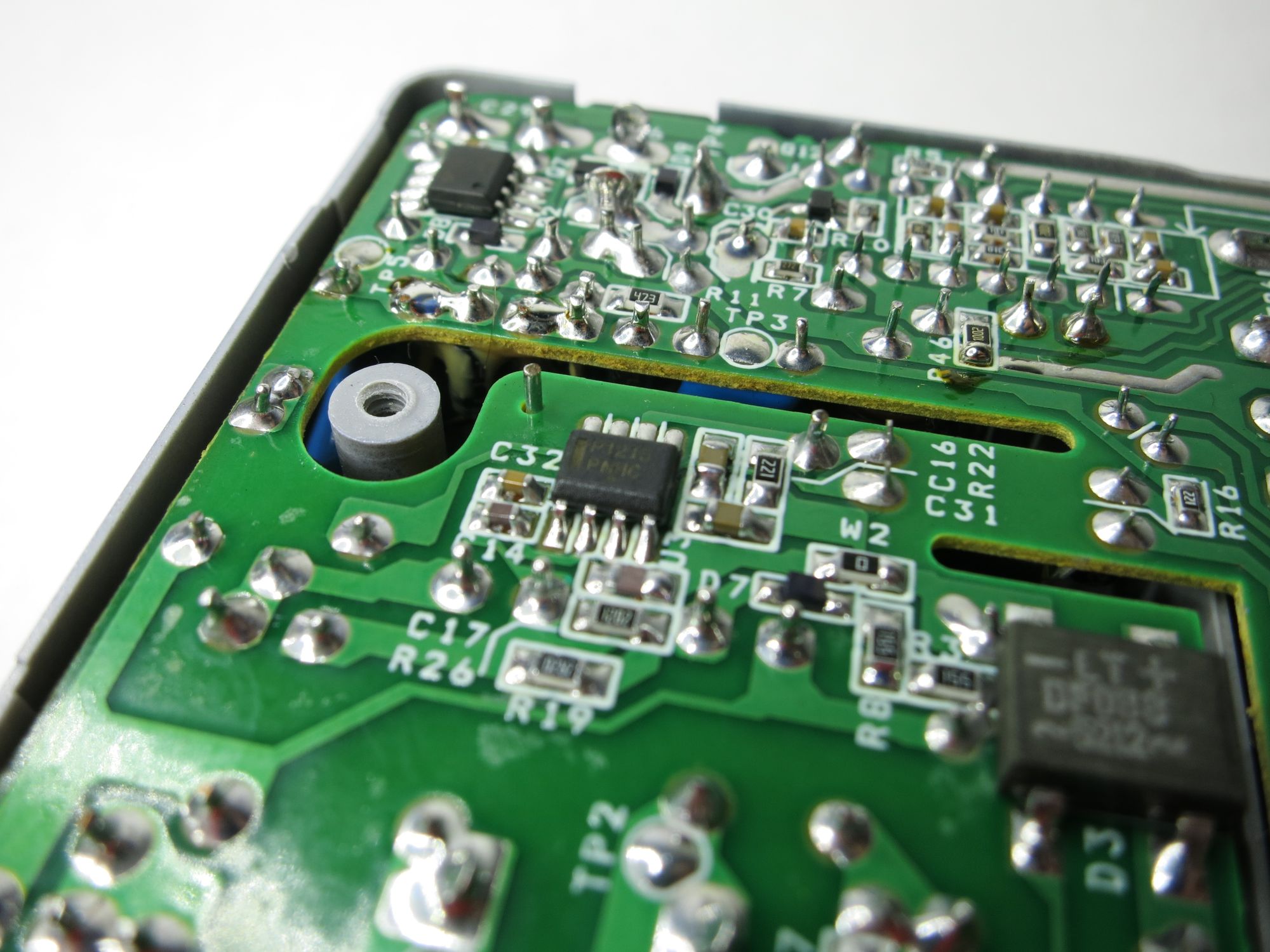
– Charger circuit, using an unknown controller IC. The markings have been shaved off. I just don’t understand why they go through the trouble of doing that… It’s not like this is some super classified product where the design should be kept secret at any cost.
A closer look at the components and PCB around where the plastic had melted does not give any clues of what has gone wrong – in fact nothing visible anywhere on the PCB indicates a catastrophic failure of the charger.
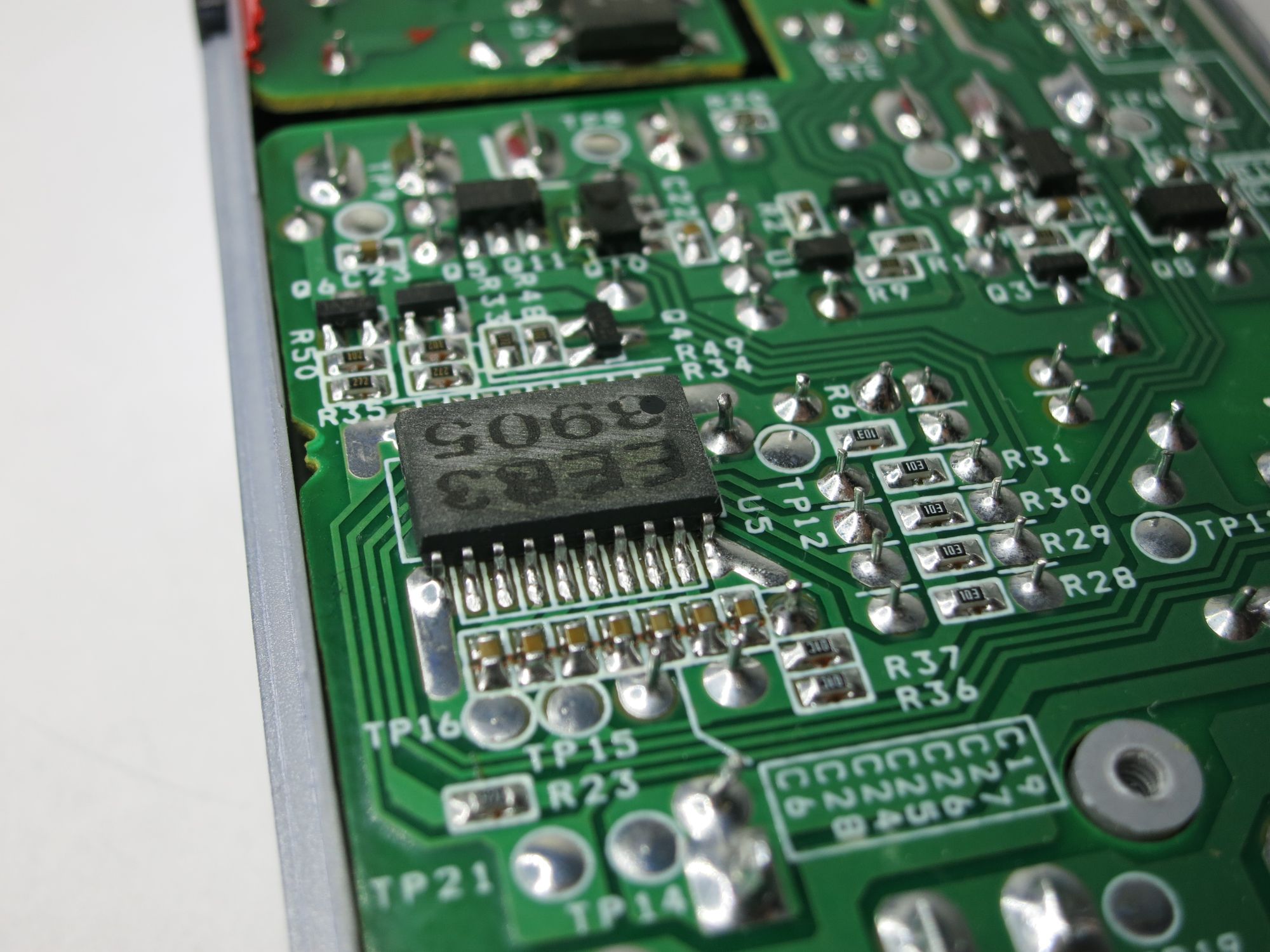
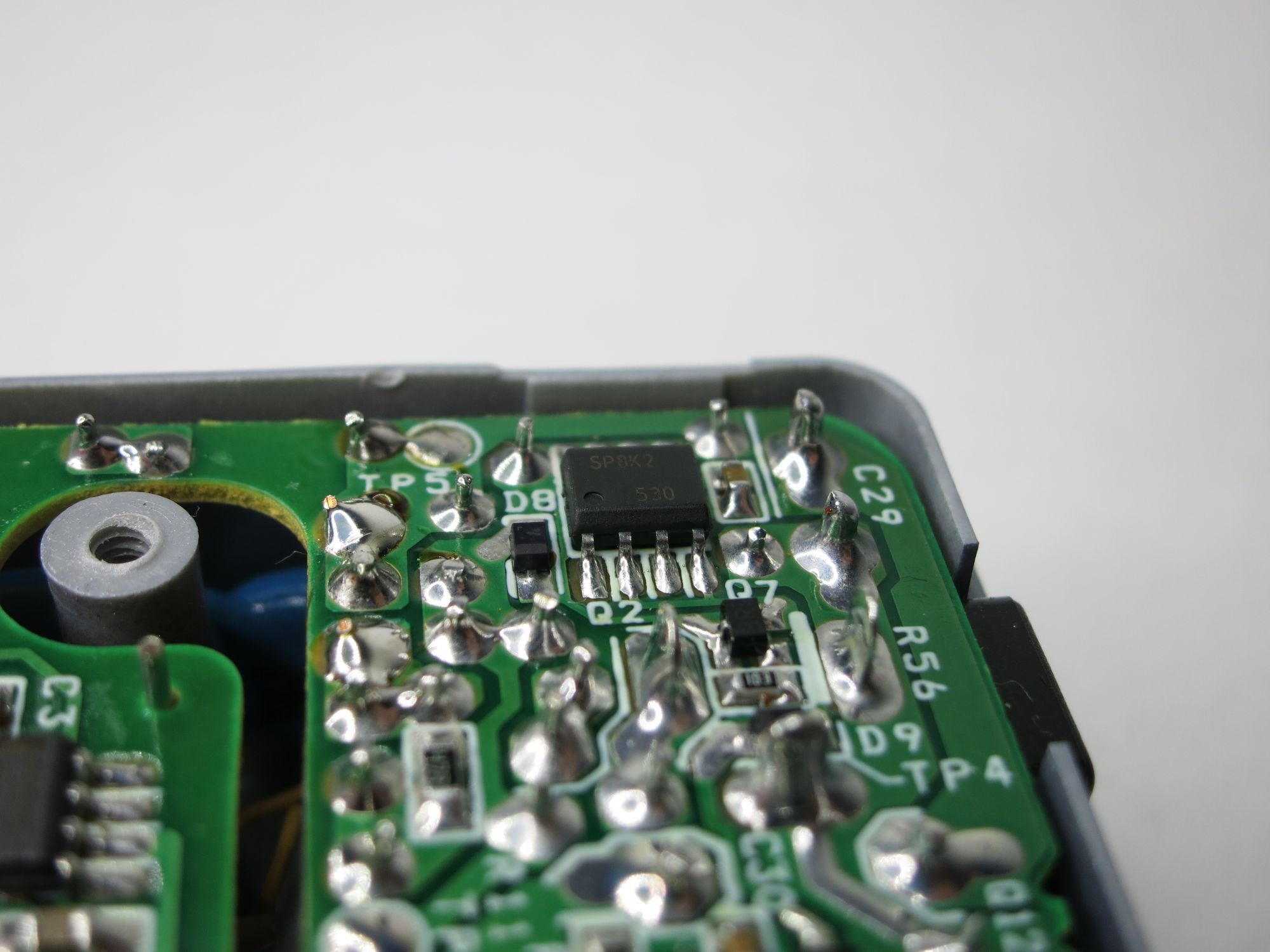
Bringing out the multimeter and measuring the output from both SMPS and 12V section shows that those voltages are all good – most likely the problem is instead in the unknown charging controller IC, or possibly some of the tiny SMD FETs, diodes etc that complement the charging IC.
So… given that this kind of charger cost next to nothing these days, I’ll leave it for dead for now. The SMPS works as it should, so maybe that part can be reused in some other project – I’ll stash it in the “possible-future-use” parts bin.