
HP 6632A power supply cleanup and modifications

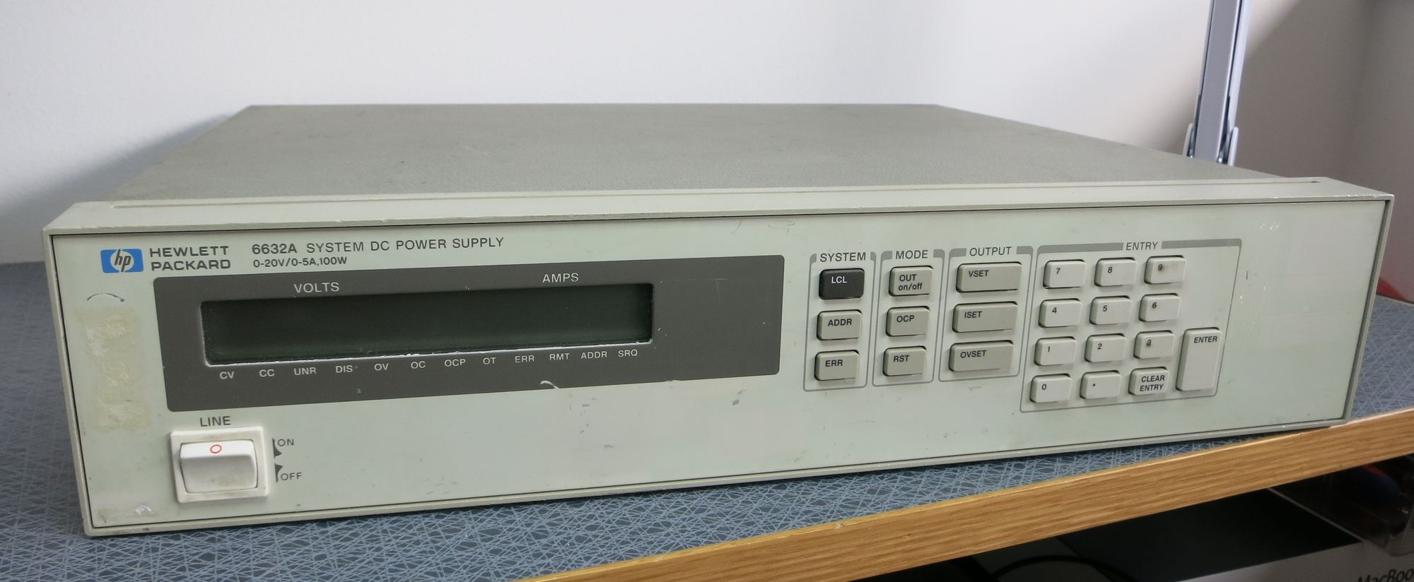
There is a new tool in the lab: An HP 6632A power supply.
It might be a a bit dated, but it has some pretty good and useful specs (0-20 V, 5 A). True, modern supplies are more compact and offer more features in a smaller box, but a major advantage of an older supply like this, is that all schematics are available, they use large, easy-to-change components, and you have a decent chance of actually understanding how they work. A great thing about this particular model is that it can not only source current, but also act as a current sink. Useful when you need to see how other power supplies behave under load.
The HP 6632A is programmable over GPIB (or HPIB – it’s more or less the same thing), but given the costs of GPIB adapters, I doubt I will get one.. Most functions of the supply can be controlled locally from the front panel anyway. A main exception is however the calibration, which requires a HPIB connection. Bummer… especially as this unit at first inspection seems to show slightly incorrect readings.
Turning the supply on it worked a treat, but it is LOUD! Checking the schematics (available in the service manual) reveals that there is no intelligent fan control – it starts at full speed, and there it remains. No matter if the supply is loaded or not. Given my previous work on fan speed control, this is a challenge too good to pass on.. More on that later. So let’s take it apart. Ooohhhh… it is INSANELY dirty inside.
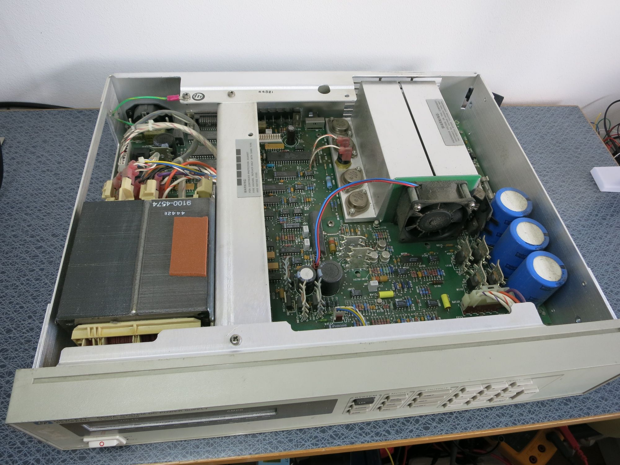
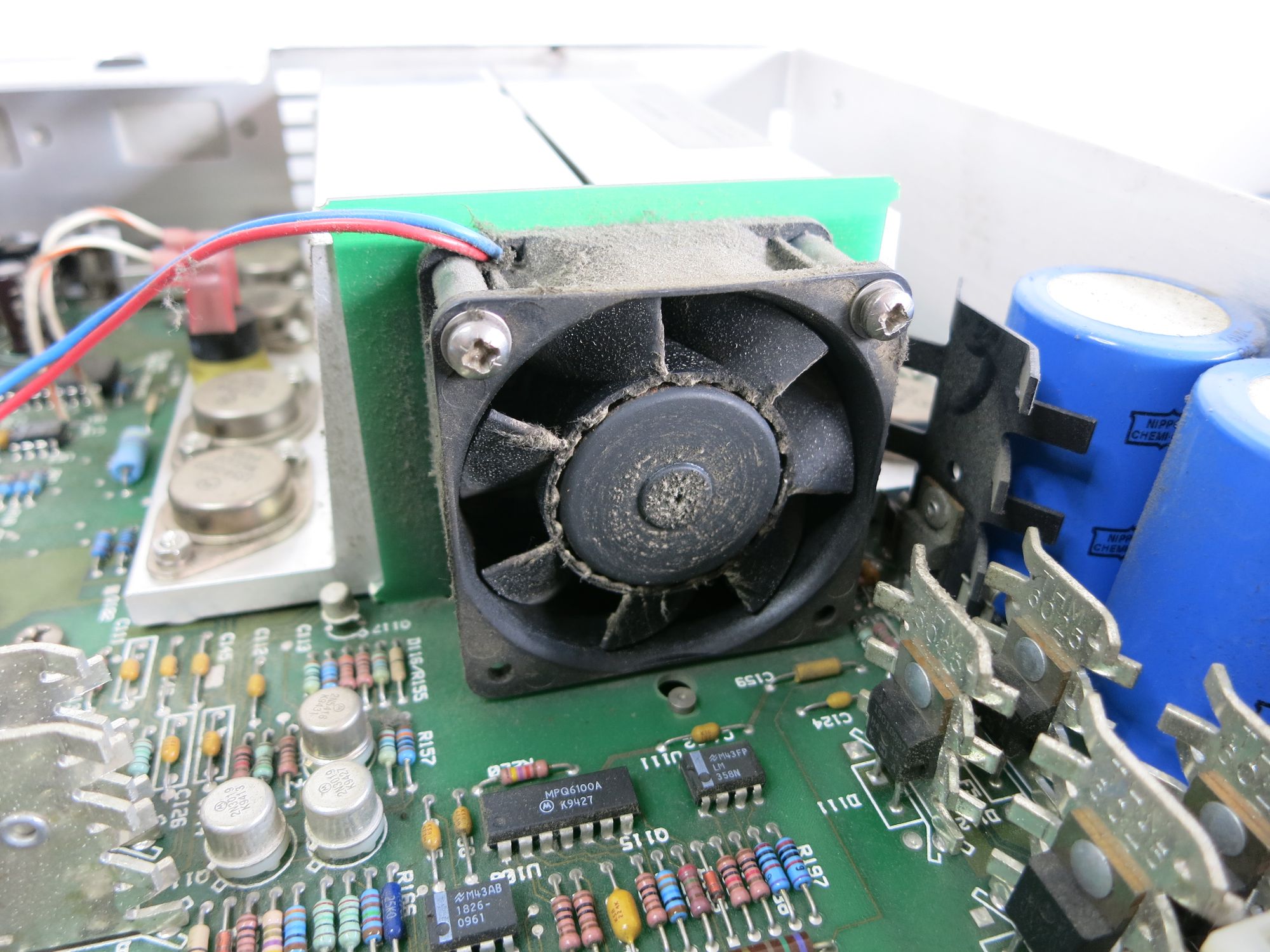
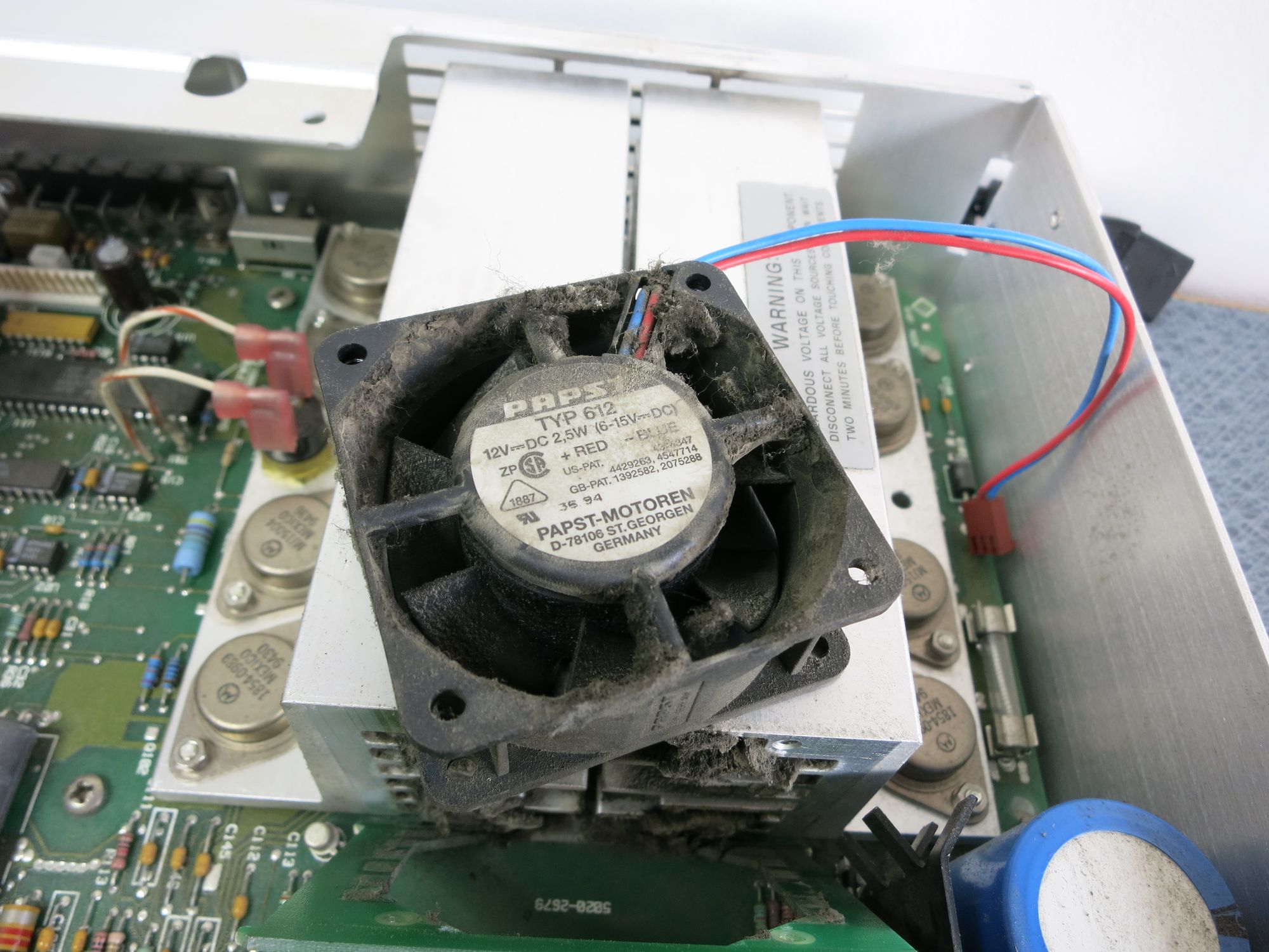
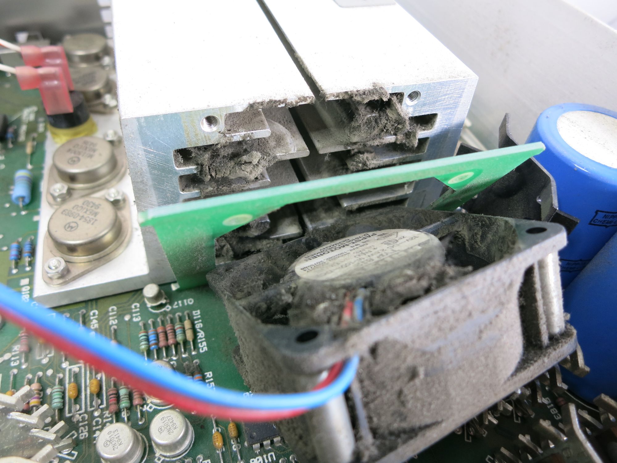
That fan is just clogged with dust and I don’t know what.. That’s got to be bad for the bearings. Sure, Papst make great fans, but this one has taken a serious beating. And all the dirt inside the heat sink.. Nasty. Time to bring out the compressor and blow all the dirt away.
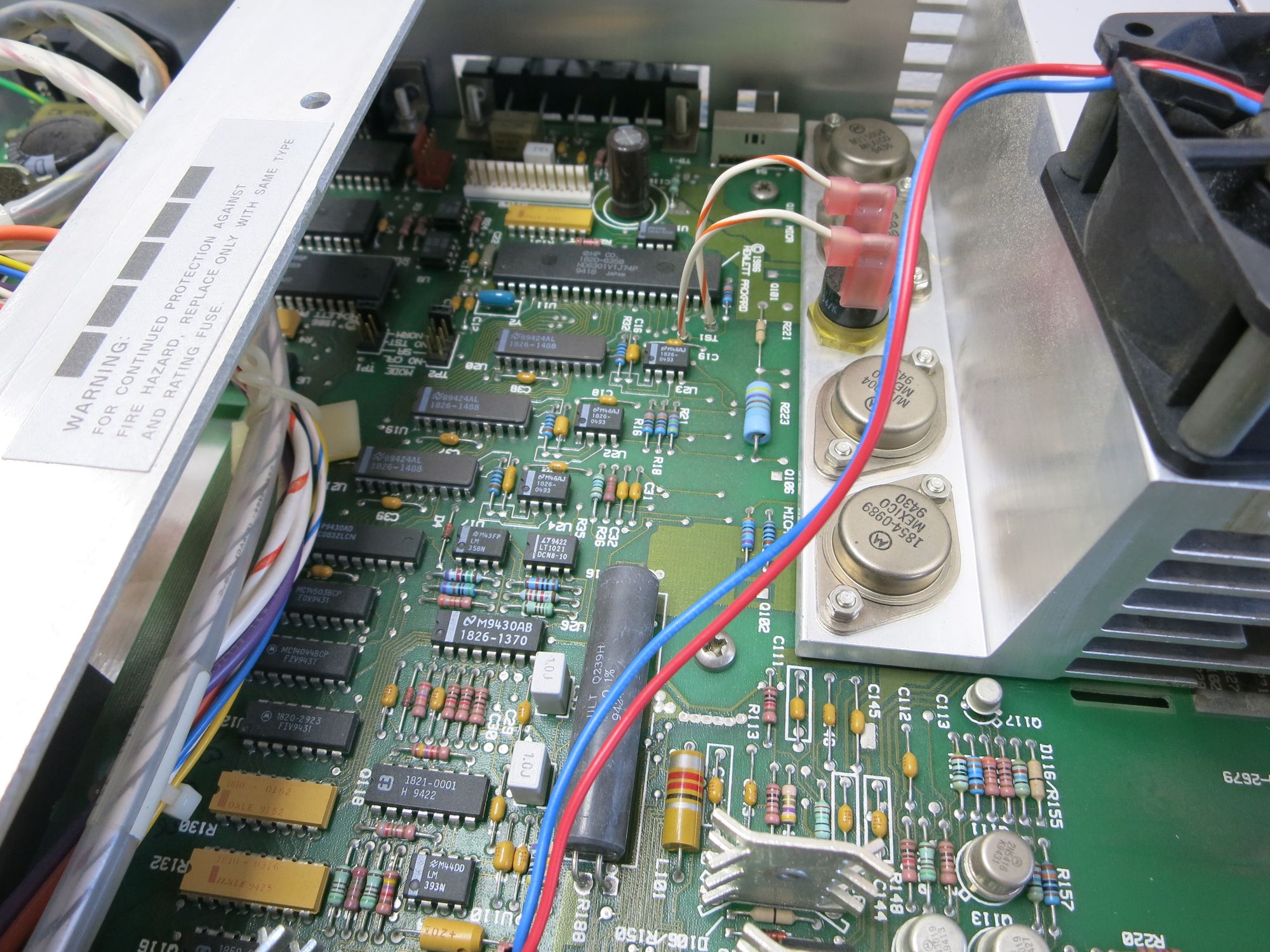
The result is pretty good – almost all dirt was removed from the fan and heat sink, at least it is way, way better than before.
The original Papst fan still sounds like a jet engine though, it is probably worth looking into a replacement. It is a 60x60x25 mm 12V fan, but the only 60×60 fans I had around here was a slimmer (ca 12 mm) variant. It is quieter, but does not provide as much airflow. Given that a) I will rarely load the supply heavily, and b) the supply has over-temperature protection built in, I am not too worried about replacing the fan. One small problem though: The screws for the old fan (they are screwed into threaded holes in the main heat sink) are too long. No suitable screws could be found, but wait – those springs that I scavenged from the first electronics kit I got when I was 10..? Hmmm… Worked a treat – almost better than the original!
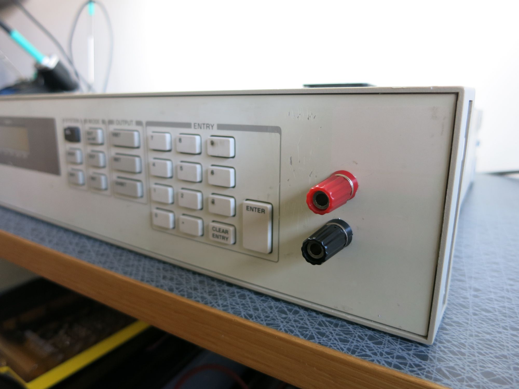
Next up: front output terminals. This is a factory fitted option (option 020) to the HP 6632A supply, but it is an easy thing to do yourself. The front panel is made of aluminium on the outside, with a plastic sheet on the inside. That plastic already has a cut-out for mounting output jacks, and there are solder tabs on the main PCB just beneath where the jacks go. Just drill a couple of holes in the aluminium and we’re good to go. But wait… it doesn’t work. The over-current protection kicks in as soon as I turn the supply on. Is it toast? No… silly mistake. The banana jacks I used were not the kind with insulated mounting. In a plastic box they would have worked nicely, but here.. they just created a short through the supply’s aluminum front panel. Duh. New, insulated jacks and all works fine.
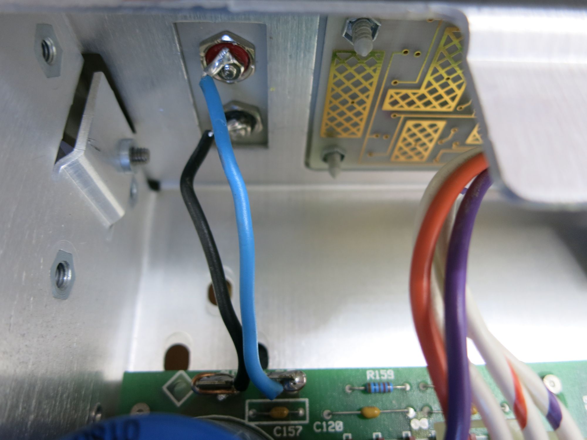
Make sure to use proper, heavy duty wires between the PCB and the jacks, in theory 5A at 20V could be flowing through there. I used the kind found in mains power centrals in residential housing, the copper is so thick it actually takes some effort to bend it. Should be plenty.
Finally, regarding calibration. Setting the supply to 5V, the display shows 4.996 V. The 0.004 V error shown by the supply itself is 0.08 %, which is actually within spec compared to the 0.05% + 10 mV accuracy (i.e. 0.0125 V at 5 V programmed level) of the supply.
A connected multimeter (Fluke 89 IV, known to be spot on with respect to multiple different precision voltage sources) shows 4.9957 V, so it appears at least the supply’s output voltage is actually within spec and calibration, after all. However, setting the output to 15 V, the supply shows 14.995 V, and the multimeter shows the same. So about the same offset as before.
It might be within spec, but there does seem to be a ca 4-5 mV negative offset in the output.
Not a problem in any way, this is not a precision power supply, and things will anyway change when loads are connected.
And with that, the supply is in a much improved shape.
It is still really heavy (not much to be done about that, I am afraid), the fan is a bit loud for continuous use, and no calibration without a GPIB adapter. Still some room for improvement thus!