Let there be (blinky) light!
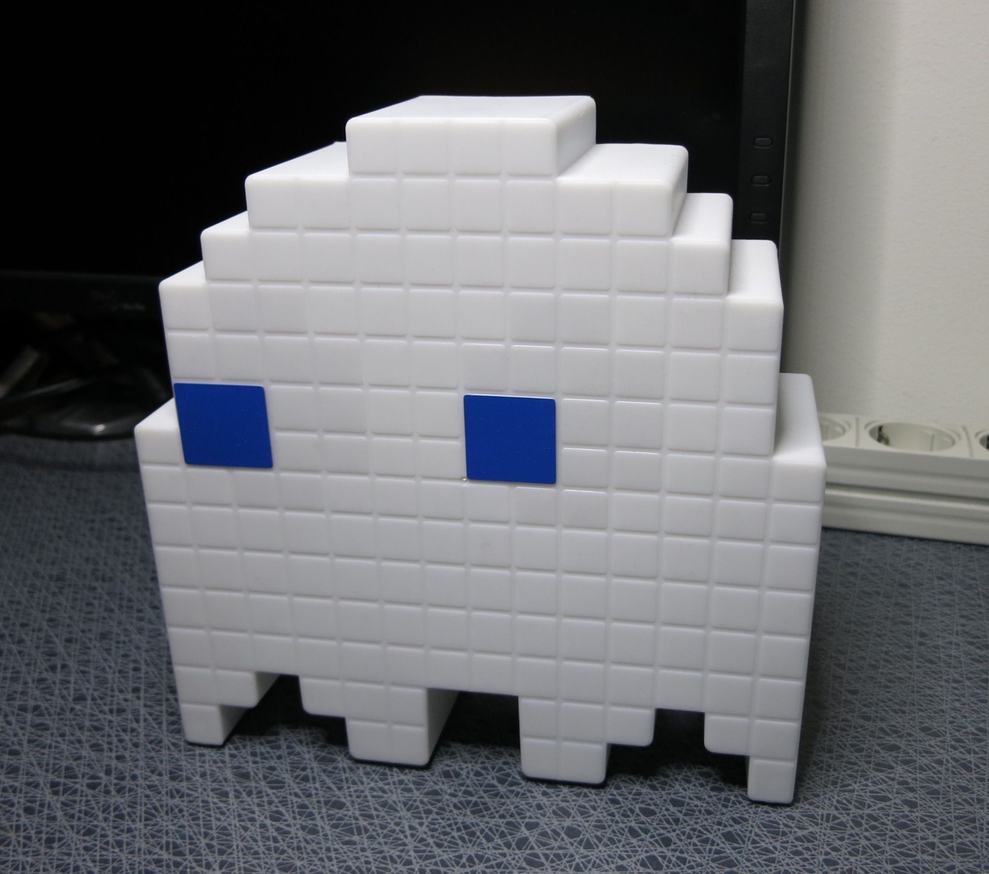
I was recently in Helsinki, giving a talk at a QlikDevGroup event. Great event, great crowd. The topic was SenseOps and Butler SOS, and I showcased the lamp above as an example of a funky, but still relevant way to monitor user activity in a Qlik Sense Enterprise environment.
A person in the audience asked how the map works. I claimed it was super simple, costing less than USD 10 to build (assuming you already have a suitable enclosure) and uses just four wires hooked up between some pre-made modules. Time to prove it.
The four wires part might have been a slight exaggeration… but it depends on which wires you count – right?
High level concept
The lamp/monitor works as follows:
- Qlik Sense uses the log4net logging framework. We can hook into this framework and get notifications when the events of interest occur. In this case we want a UDP message to be sent when a connection to Sense is open/closed, and when a new session starts/ends (for an existing connection). This is achieved by placing an XML config file in a specific folder on the Sense Enterprise server, see the Butler documentation for more info on this.
- The UDP message is sent to the Butler service. Butler hosts several different micro services, one being a UDP server that receives the message from log4net.
- Butler forwards the connection open/close and session start/end messages to well defined MQTT topics (as defined in the Butler config file).
- The lamp’s brain consists of an ESP8266. This is a wifi-equipped microcontroller, which subscribes to the MQTT topics (using wifi). Once messages arrive on these topics, the lamp animates the LEDs green or red, depending on what message arrived (and on what topic the message arrived).
It is assumed there is an MQTT broker available. Installing Mosquitto is very easy though, so this should not be a showstopper.
The result is a lamp that has animated light effects reflecting user activity on the Sense server. When a user opens a connection or starts a session on the Sense server, the lamp shows an animated green sequence.
When a connection is closed or a session ends, the animation is instead red.
If you power the ESP8266 and LEDs from a battery you will have a fully stand-alone unit – otherwise you will need to provide power using a USB cable. Note that the cable is used only for power – all communication goes over wifi.
The parts
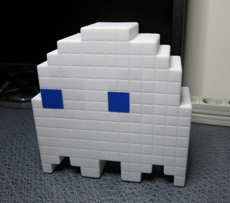
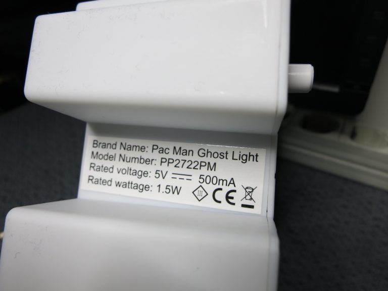
First we of course need a suitable gadget to convert into a Sense monitor. I use a kids night lamp in the form of a Pacman ghost – but you can of course use any suitable enclosure.
As an example, I have an industry grade signal lamp here that is due for conversion. I got it from a surplus site on eBay, similar to this product.
The blinky side of things comes from a couple of RGB LED strips.
I use WS2812 LEDs (a.k.a. NeoPixels) as there are many existing, easy to use libraries available for driving them. They are also very easy to get hold of – you find them all over Ali Express, Ebay, Amazon, Adafruit, Sparkfun etc.
Search for “ws2812 5050” and you should find what you need (make sure to get LEDs already soldered onto a flex-strip or PCB, rather than the individual LEDs). For no particular reason I used two of these.
Works well.
Then we need a computer to drive the whole thing.
In this case I used an ESP8266 microcontroller. ESP8266 based boards appeared on the market a few years ago, they cost just a few USD and have dramatically lowered the barrier of entry for creating wifi enabled products.
The exact name of the module I used is “D1 mini pro” from a company named Wemos, you can buy them off Ali Express (and elsewhere). Any ESP8266 based module should work though, there are plenty of them.
Make sure to use a module with 16 MByte flash though, otherwise you may runt into trouble when sending your program to the device over wifi.
Also known as “Over The Air firmware update”, or OTA update. Embedded electronics has its own lingo, sometimes…
Some wires are also needed, no specific requirements there. Use what you find in your junk drawer. Connecting the wires to the microcontroller and LEDs will require some soldering.
Finally, you need an IDE to develop the code in. I tend to use PlatformIO for projects like these. It integrates into Atom (and a bunch of other IDEs). Plenty of good libraries available, together with super easy OTA updates of your device. Very nice.
As you probably have figured out by now, I assume you have a working knowledge about IDEs, C programming, soldering etc. If not, Google is your friend, as always.
The schematic
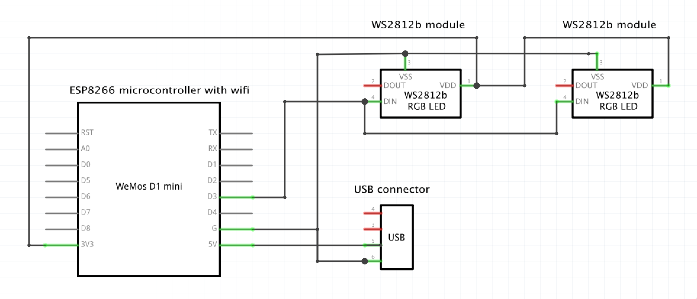
Using Fritzing to create a conceptual schematic, the result is as follows. Depending on what you want to achieve, you might also want to add a power switch, fewer or more LEDs depending on how complex animations (if any at all) you want to create etc. I chose to integrate the Sense monitor with the ghost lamp’s existing electronics, making it possible to switch between the lamp’s standard function/mode, and the Sense monitor mode. I use two PCBS with eight WS2812 LEDs on each. The two PCBs are connected in parallel, as seen in the schematic. This is a slightly unusual way of connecting these LEDs, but it works. Also, I drive the LEDs with 3.3V, which is less than their recommended VDD voltage. But once again – experience shows that it works.
Fritzing also offer a breadboard view of your circuit. Not anything an experienced hardware engineer would ever use, but maybe useful when getting started with embedded electronics:
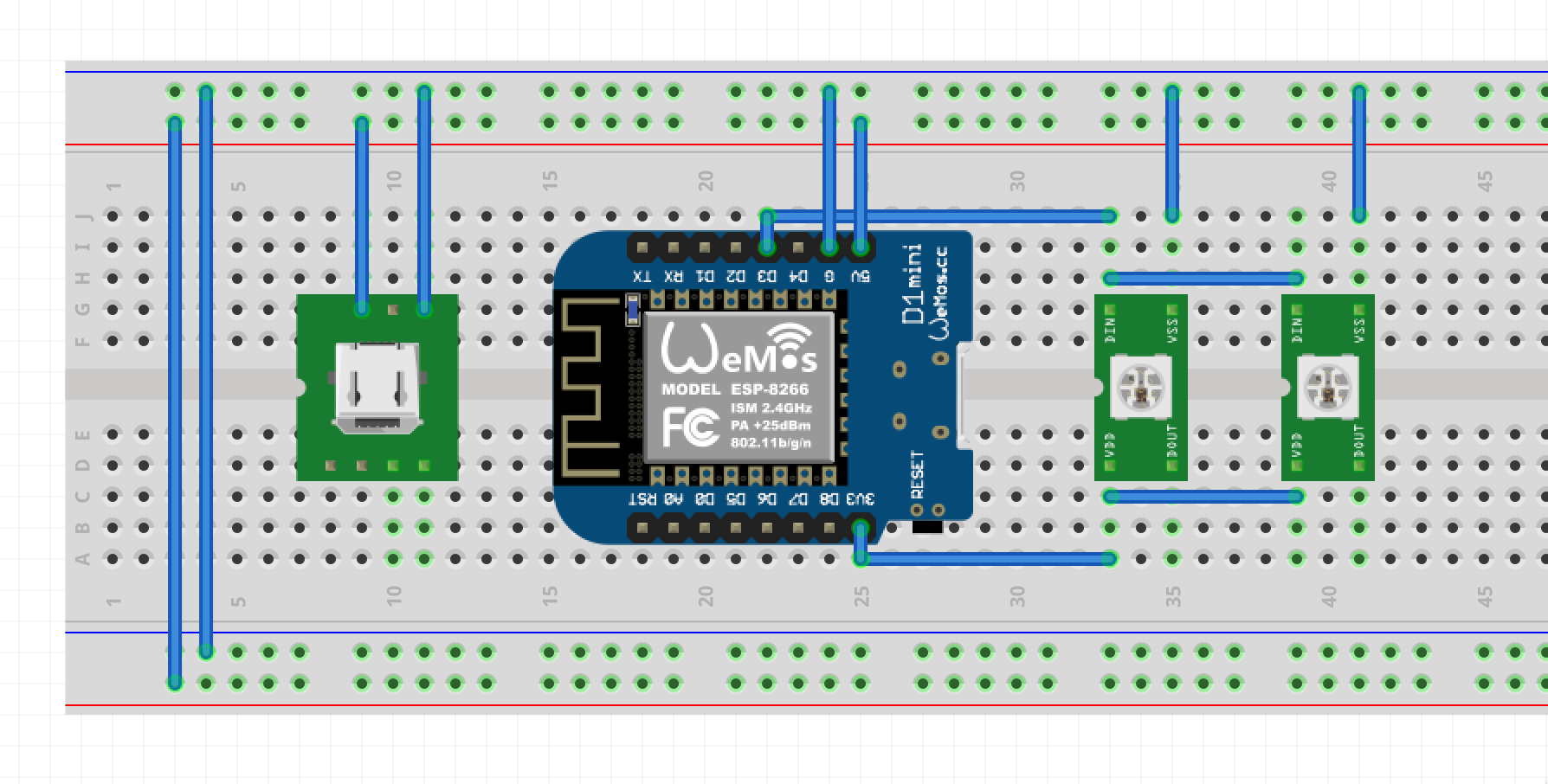
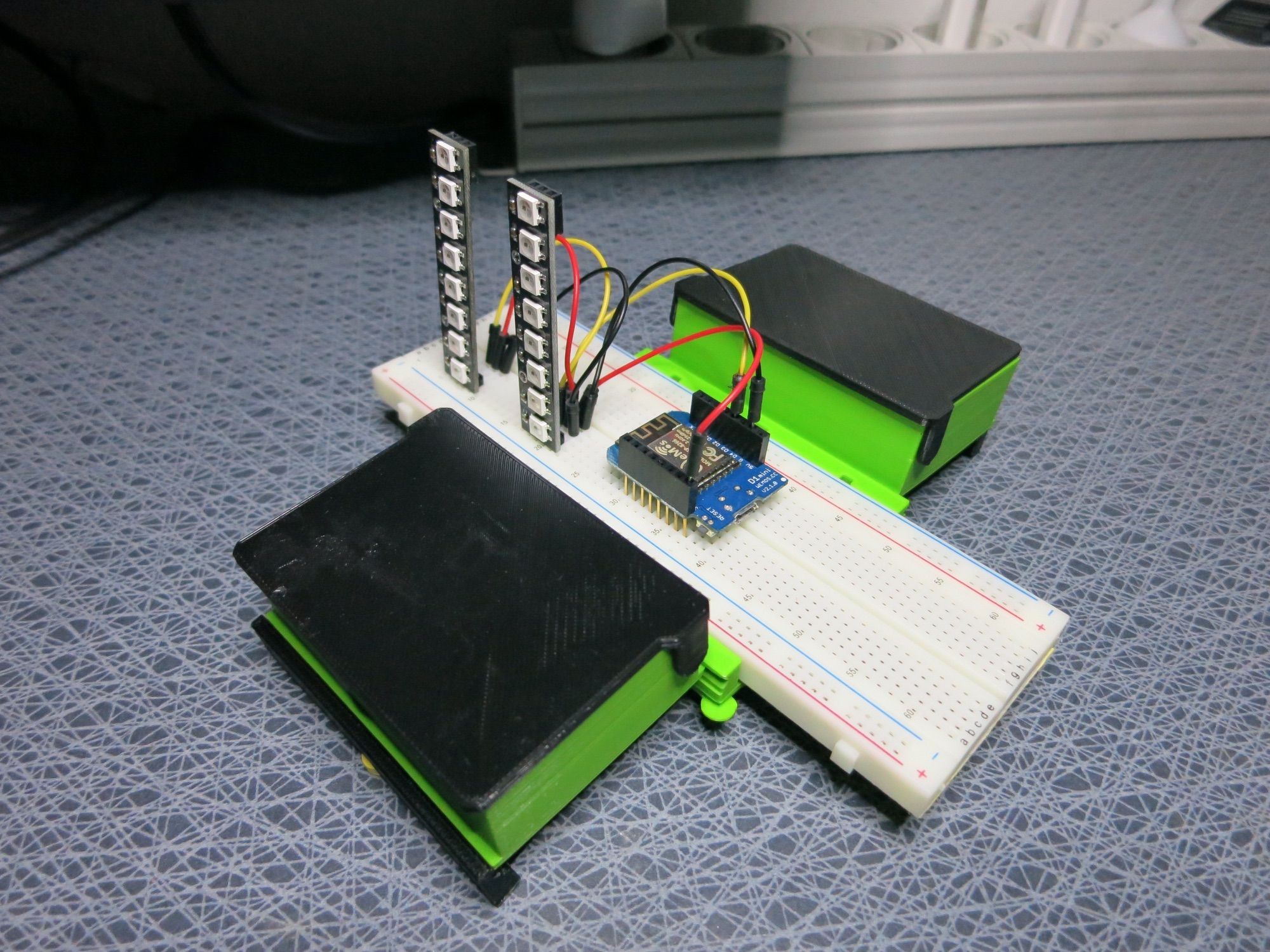
Speaking of breadboards – it is always a good idea to verify the circuit on a breadboard first. Once it works there, you can glue the components into place in the gadget, and soldering everything together.
The green/black boxes are just for storage, they are however very useful for keeping project related parts. 3D printed from this Thingiverse project.
Connecting the pieces
Time to take the Pacman ghost lamp apart, and see how the Sense activity monitor can be integrated into it.
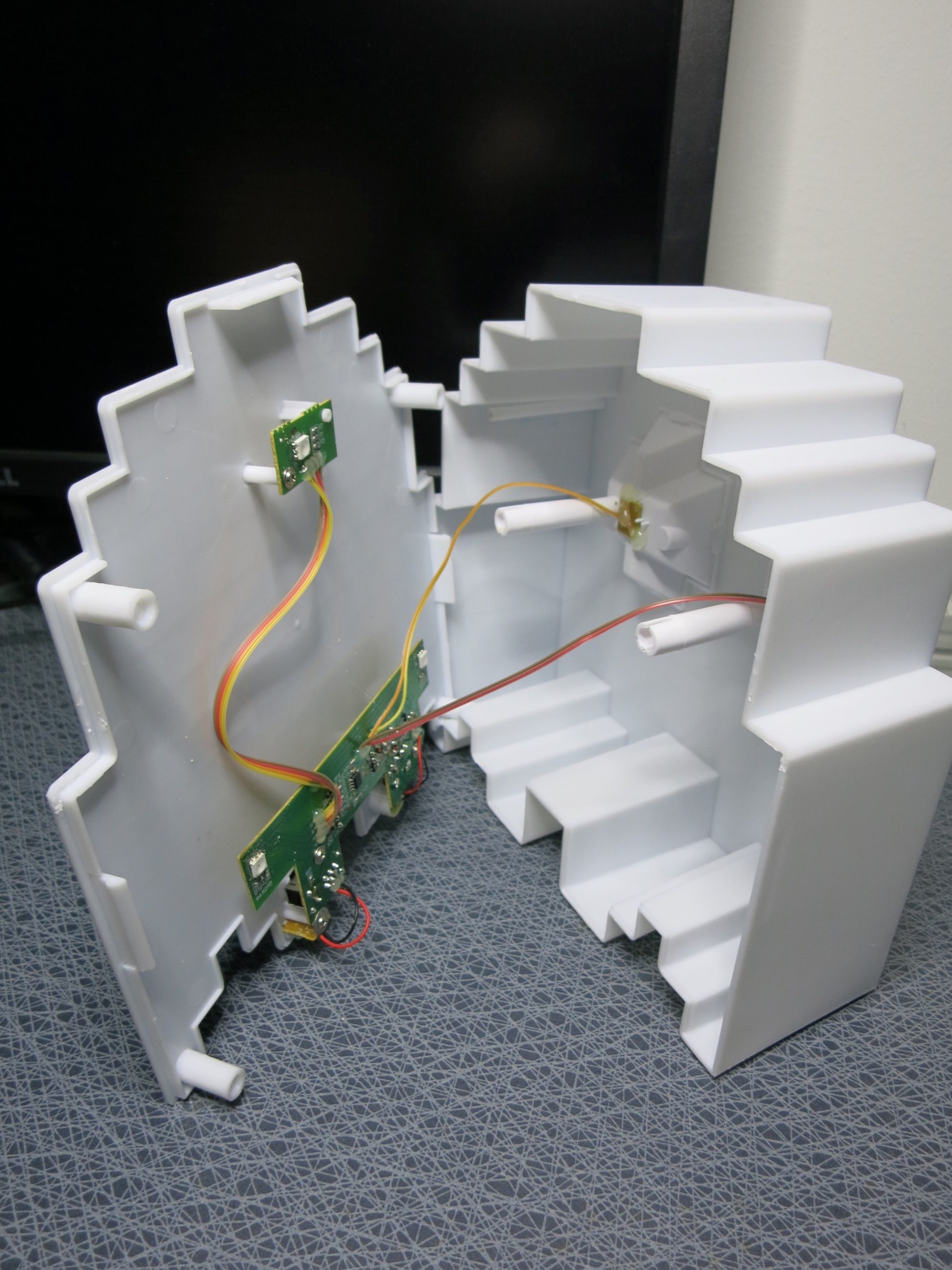
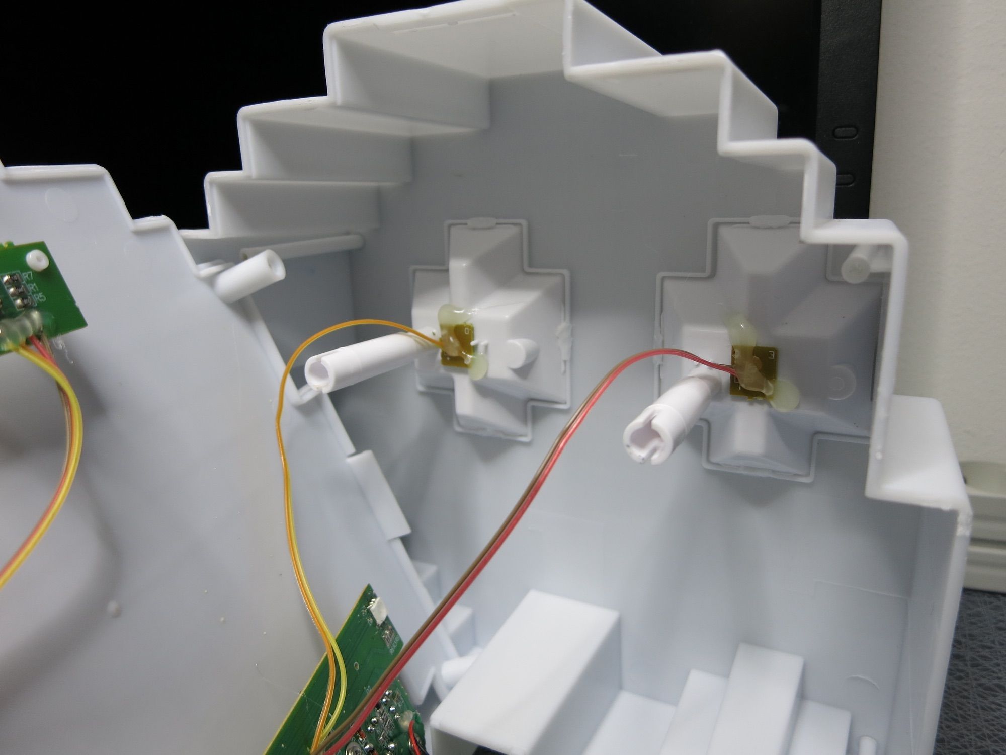
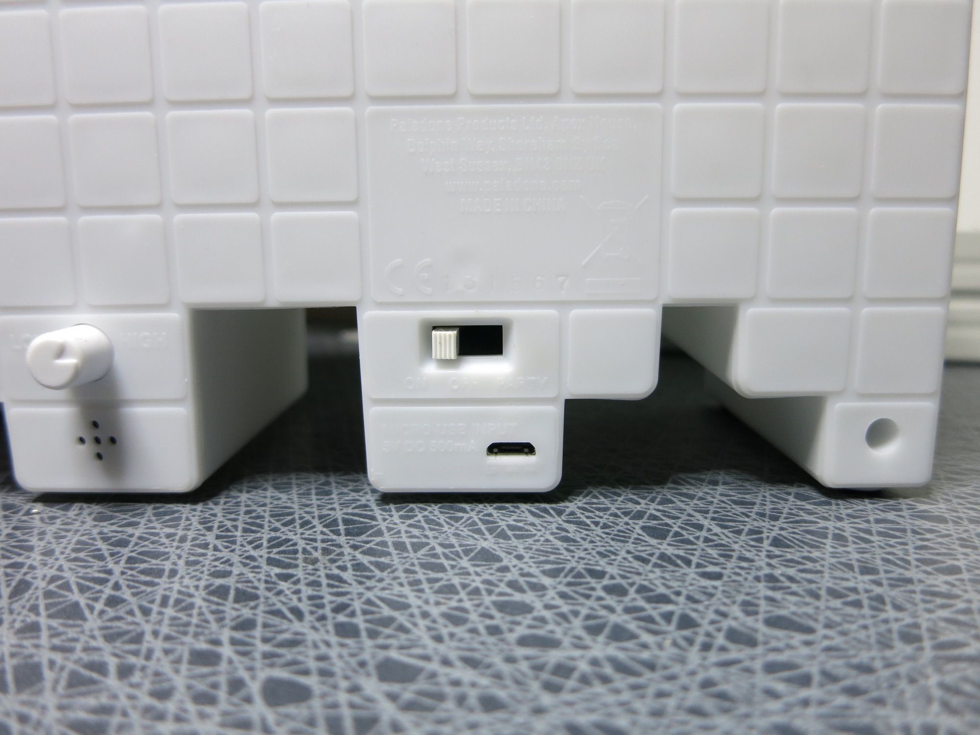
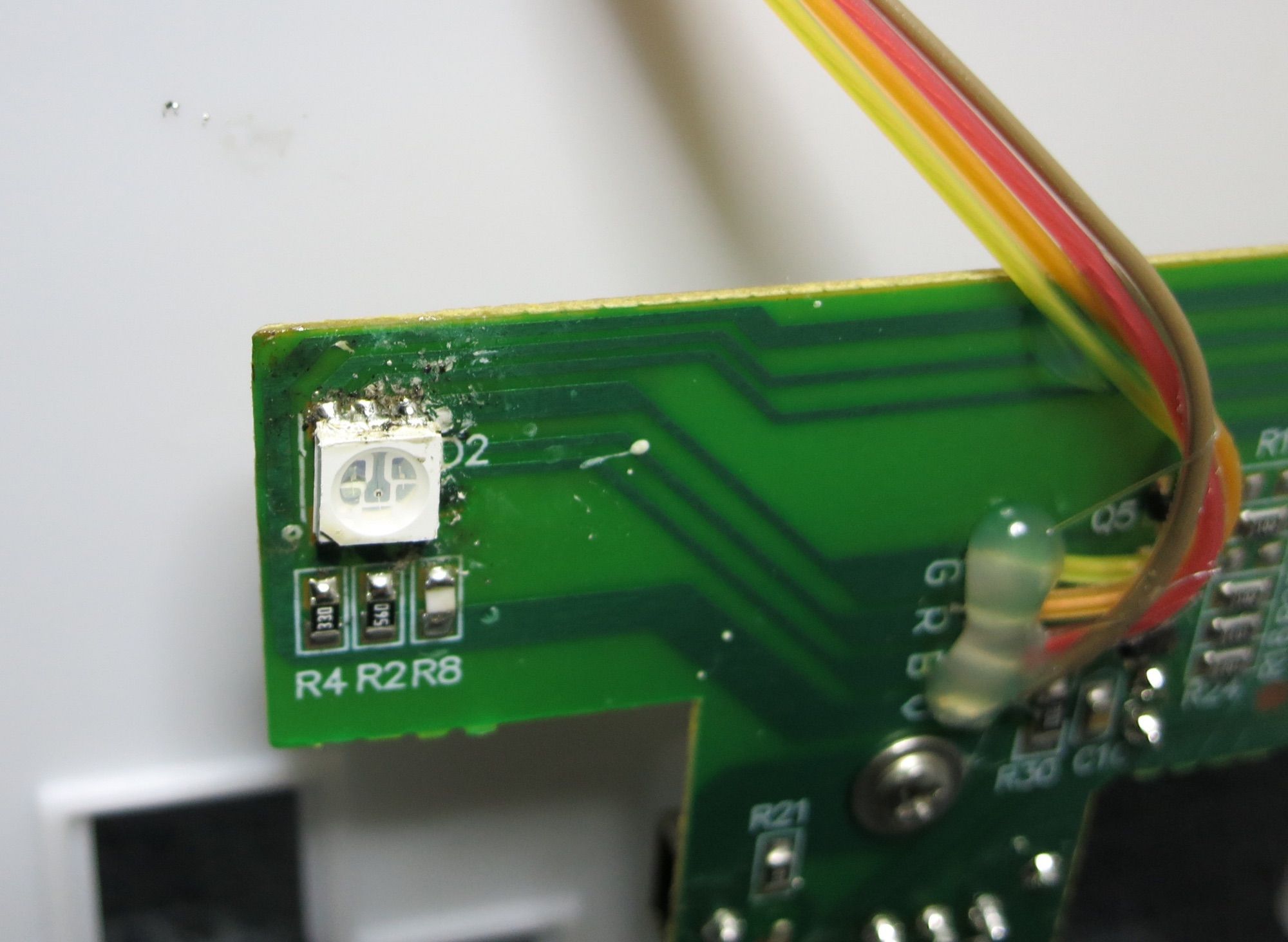
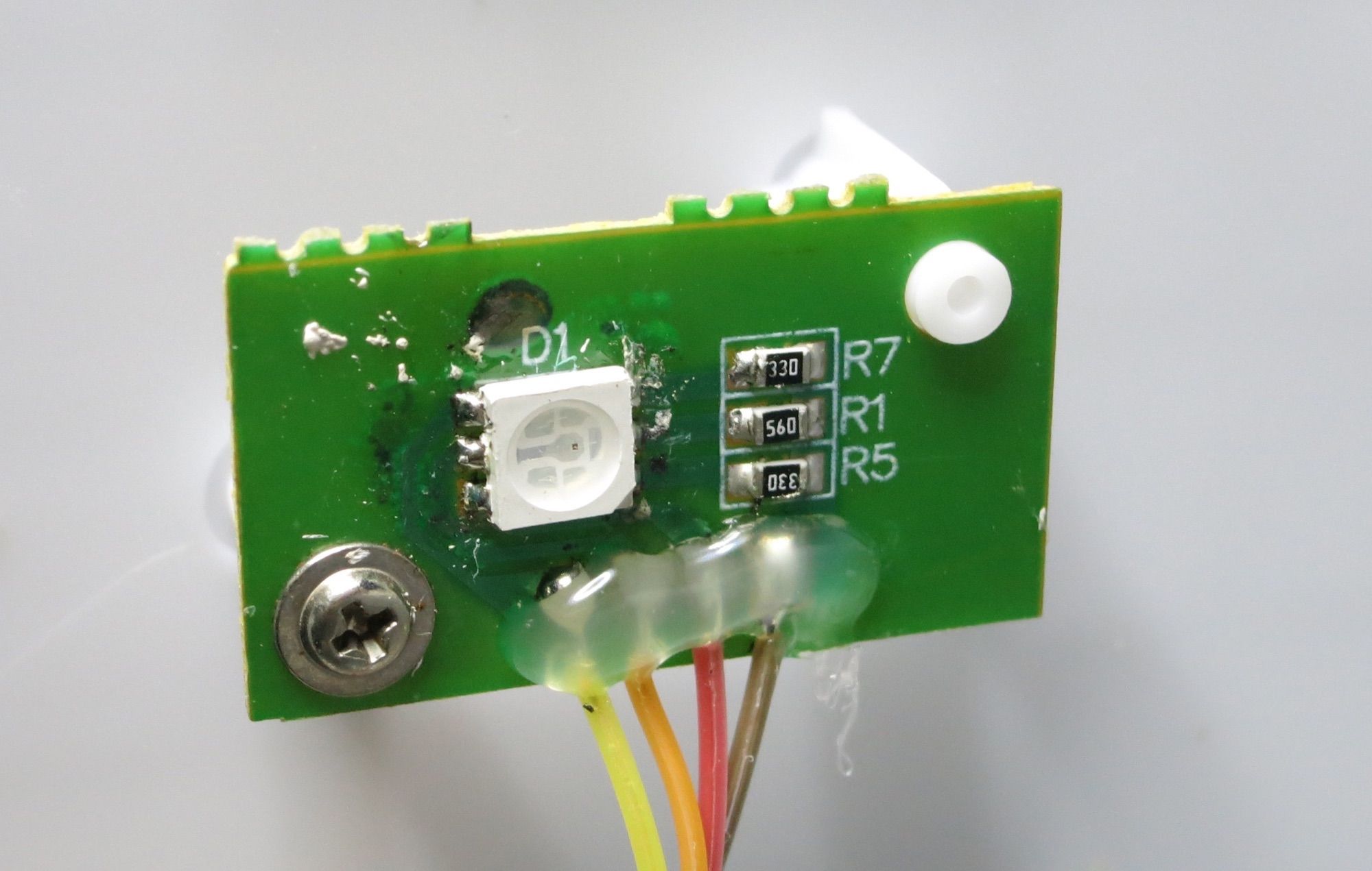
So far so good. We can get power from the existing USB connector, and also add a basic 2-way switch that make it possible to switch the lamp between its original function, and being a Sense activity monitor. This is of course not strictly needed for the activity monitor – I just thought it would be nice to keep the original function of the lamp too.
After glueing the ESP8266 module and the two LED boards in place, the lamp’s interior looks like below. I was lazy and used cheap wires with Molex connectors (bought from some random eBay store) where possible, and soldered the rest of the wires.
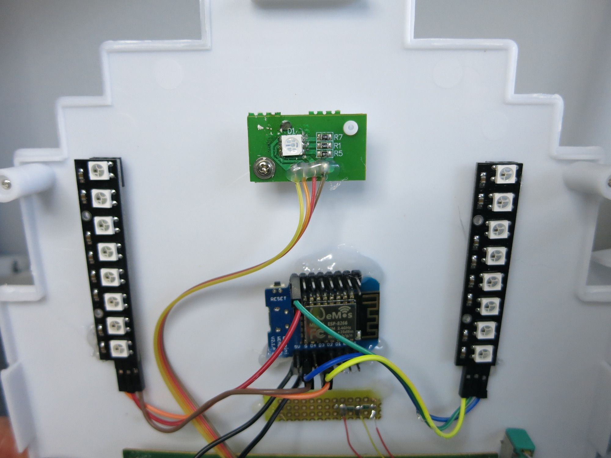
The fact that the lamp uses modules with 8 LEDs in series, means that the ESP8266 can create basic animations on the 8 LEDs. The WS2812 library used has a set of different animations, feel free to explore them.
As the modules are connected in parallel, the same light animations will be shown on both.
ESP8266 software
The code for the ESP8266 is available on GitHub. You need to install PlatformIO to compile the code and upload it to the ESP8266. First upload needs to be done over USB (preferably with the circuit still on a breadboard), later uploads can if so desired be done OTA. Please see PlatformIO for instructions re OTA uploads.
Final thoughts
It is worth noting that the lamp can be used together with any MQTT messages, not only those coming from Butler (and Qlik Sense). You can easily modify the ESP8266 code to use other MQTT topics, and instead function as a monitor for load levels of some server (Windows, SQL, Linux), when someone presses the MQTT connected button at your office front door, etc etc etc.
I have some vague plans of adding a LiPo battery to the lamp, together with a USB based charging circuit. The lamp could then be charged, after which it would operated without any connected wires at all. There is plenty of room inside the lamp for a battery and charger module – should be pretty straightforward.
The only remaining recommendation is simply: make sure to have fun!
