Reverse engineering Macbook Air FaceTime camera, part 1
A severely cracked 13″ Macbook Air display came my way some time back. The LCD panel was obviously damaged, but it would be interesting to see what makes such a great display tick, and maybe parts of it could still be used? I believe the display came from a Late 2010 Macbook Air (which would indicate an A1369 type construction), but can’t be sure. Anyway – ideas included
- Keeping the back lighting (assuming it works) and camera, mounting the whole display on a flexible arm next to the work bench. Given the high intensity of the back lighting, it could then (maybe) provide ambient lighting AND video recording of whatever was being worked on. Maybe with a LED light and camera on a separate flexible arms.
- If the LED backlighting drivers were toast, there should still be some nice white LEDs in there for scavenging.
- Same thing for the camera, I believe it to be a 640×480 pixel device, nothing too exiting but could still be useful.
Turns out it’s not entirely easy to disassemble these displays. They are sealed together with very strong tape. Heating the bezel helps a lot, but it’s still a fair amount of work – and given the delicate components beneath the bezel, you might want to think twice before doing this on a laptop you care about.. Some good instructions found here, btw. Results so far:
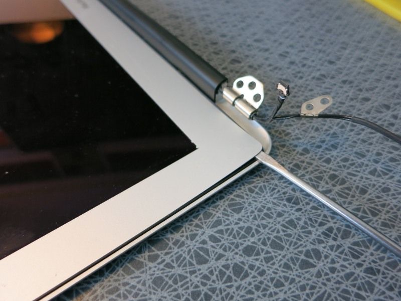
…before applying heat with a hot-air SMD rework station (regular heat gun would probably also work, if you are careful):
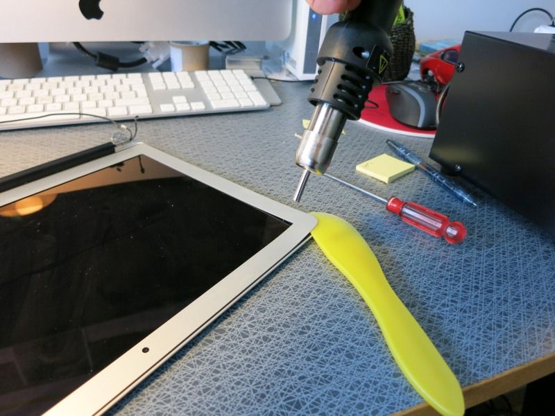
Voila! Bezel is free:
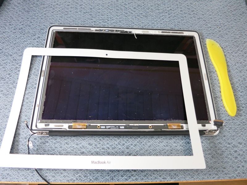
Now the tricky part. The cable from the cable is a thin wire with some kind of textile cover, for strengths I assume. It goes through the hinges and there is no way (as far as I can tell) to get the cable through there, without cutting off the (very small) connector that normally connects to the computers Left I/O (a.k.a. LIO) board. Cut.
Now the whole camera assembly can be removed. It also includes the ambient light sensor, which communicates over I2C. Unknown protocol for that one though – one for the future to investigate..
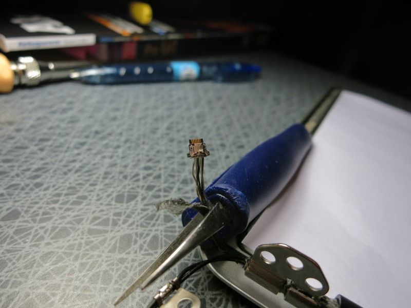
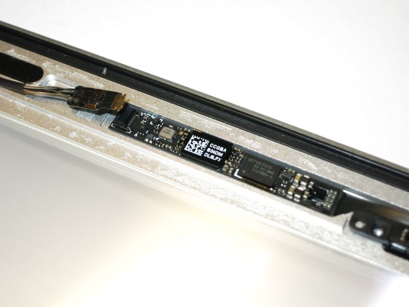
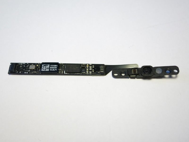
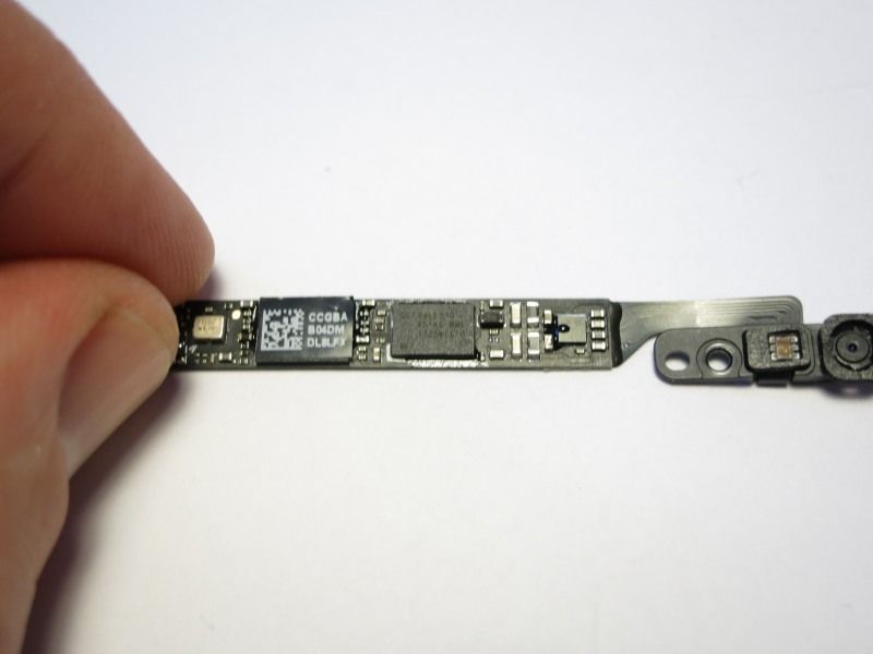
With six wires in the cable it’s pretty clear that 4 are for USB (+5V, Gnd, Data+, Data-) and 2 for I2C. That cable is however crazy small – it’s about 2 mm diameter. Once the outer layer is off, you see 6 even thinner cables. 2 are black, 4 transparent. Which ones are which?
Google is your friend. Turns out there are schematics to be found if you Google long enough. Turns out you need schematics for the LIO board though, in order to get the pinout of the camera/ALS cable, and it’s nowhere to be found for the A1369. Did find a schematic for the A1370 model though (same computer but 11″ screen), with a bit of luck that cable is the same between models.
The 2 black ones are prime candidates for +5V and Gnd. Cutting away the insulation revealed that the cables are shielded, with a center wire that is barely visible to the eye. It took several attempts before I had separated the wires from the sheilding, and then done the same with the other 4 wires. Soldering these onto an old USB cable was then easy (but ugly!!):
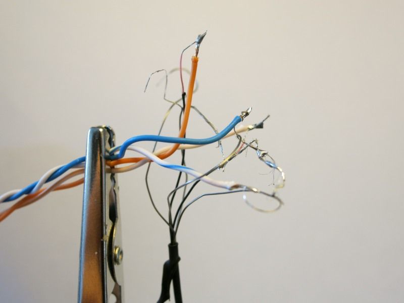
Still, it doesn’t work. The camera is not recognised on an iMac with latest OSX, nor on a Windows 8 laptop. Happened to have a Raspberry Pi lying on the work bench, tried it too with same result: nothing.
But wait… doing a “tail -f /var/log/messages” on the RPi showed that it DID recognise the camera, but that the camera wanted more power than a non-powered USB hub could provide! Placing the camera into the RPi’s regular USB port made it appear nicely when doing a “lsusb” command.
Still, it didn’t work when I connected the camera to the Windows or iMac machines – strange.
Also, the RPi loose contact with the camera after a while – no idea why. Could maybe be a bad USB cable (it’s from an old mouse using USB 1.1 – maybe that’s a problem??), or is there too much noise introduced by the ugly splicing of cables that I’ve done? No idea… More investigation needed. Anyway, the camera enumerates with USB id 05ac:850a, which indeed is an Apple FaceTime camera – nice!
