On this page
A while back I got a free PCB from Dangerous Prototype’s Free PCB program. It’s a nice little board designed to provide easy current monitoring during prototype stages of a project. Features include over-current tripping with visual indication, as well as dual 5V and 3.3V supplies.
So, a week or two ago I was about to reverse engineer a laptop camera (built with very small components…). The camera’s attaching cable has unknown pinout, but system block diagram indicate it’s a USB 2.0 device. The cable is a 6-wire variant, so it shouldn’t be too hard figuring out which wire does what. It would however be nice to have a controlled power source feeding the camera during the work.
Enter the smoke tester… I figured I would build it, to the extent possible, with parts already found in the lab, if needed maybe even scavenging some old computer or similar..
The result is pretty nice:
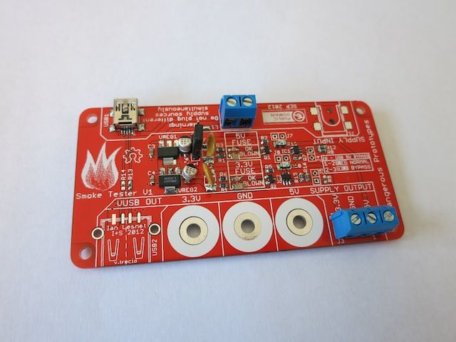
Some comments/feedback on the design:
- Input power screw terminals don’t have +/- marked on the board.
- Holes for bana jacks too small for any of the jacks I’ve tried.
- Really nice with the three parallel pads for INA 138 load resistors. They give good flexibility for selecting shunt resistors for the INA 138. For example, I used a 0.1 ohm (instead of 0.075 ohm as suggested in the schematic) shunt resistor, which means the load resistor should be 50 kohm. Easy – two 100 kohm resistors in parallel does the trick.
- Documentation is very limited, basically just a forum thread and schematics (that don’t include all component values, e.g. R13 and R14.
A few components are missing on thew board:
- USB out connector. I had a hard time finding an SMD connector that would work. Figured I’d mainly be using the screw terminals anyway.
- Banana jacks. Going through the parts bins here, all the banana jacks were too big to fit in the PCB’s holes. Those wholes could be a bit larger, IMHO.
- Input power jack. Couldn’t find a suitable SMD one, but as I will be taking power from a wall wart with USB output I will be fine.
- R13, R14. There is no value for these in the schematics (as far as I can tell), leaving them out thus. But as the USB out connector is unpopulated anyway, it’s not a problem (right now). Edit: They should be ca 20 ohms.