Superprobe meets vintage multimeter


One of the first tools I built myself many, many (decades!) years ago was a logic probe. At the time things like yellow LEDs were still a bit rare and cool, but this baby had both red, yellow and green LEDs to indicate TTL logic levels. It was a true rat’s nest of wires – and everything stuffed into one of those plastic cases for one-time travel toothbrush that you (used to) get at some hotels. A stiff copper wire was glued to one end of the case. Ugly as h-ll, but it worked quite nicely.
Years have passed, and I actually found that probe a year or so ago. It still worked, but with access to things like multi-channel logic analysers and digital storage oscilloscopes, that probe was sent to rest at the place where electronics never return from.
Still, the basic concept of a logic probe IS kind of nice. And as some people have taken this concept and extended it to include a bunch of other tools in the same circuit, I thought I’d spend some time building a new probe.
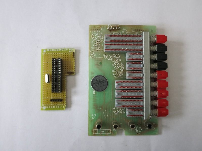
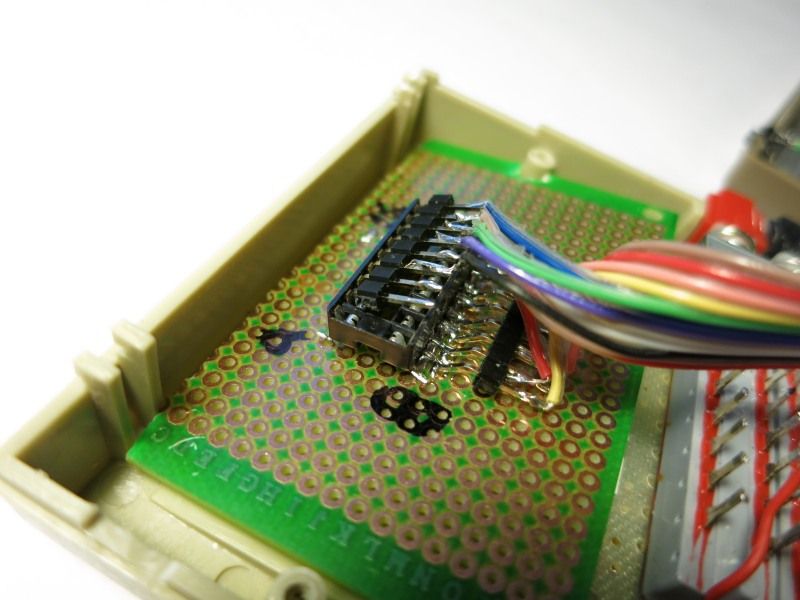
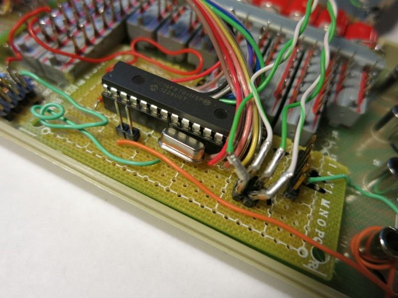
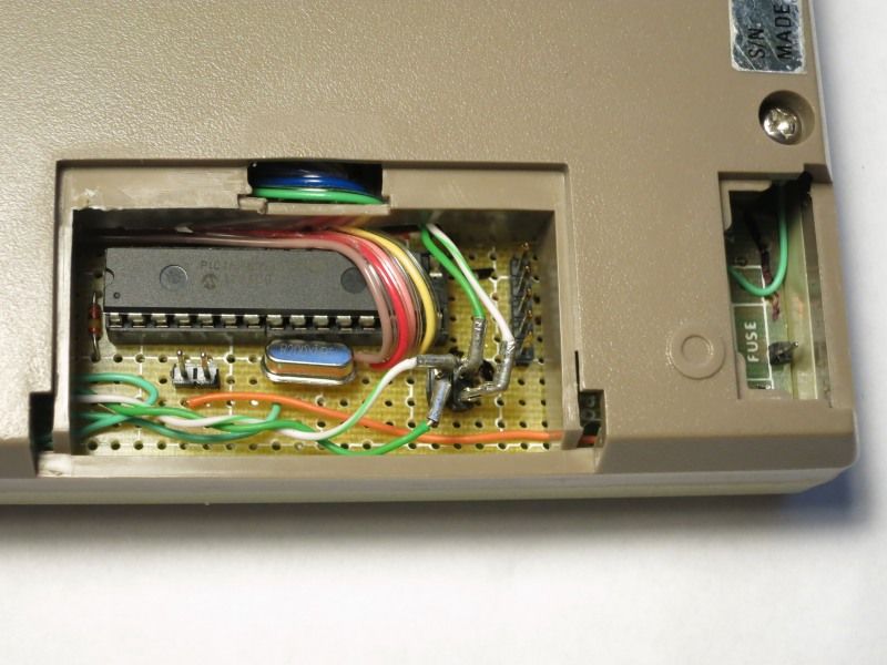
It’s really just a Superprobe in a somewhat unique (probably not, but I like the concept..) case. The Superprobe exists in various flavours, the ones I’ve liked best so far are the original one, the MKII one, and the one from Dangerous Prototypes. The one I built is a mashup of the three, dropping the voltage reg (as I feed my probe from a USB cable, which provide a stable +5V that the PIC can use. Adding programming headers á la the DP probe was a must-have. But dropping the display resistors, seems to work just fine without them.
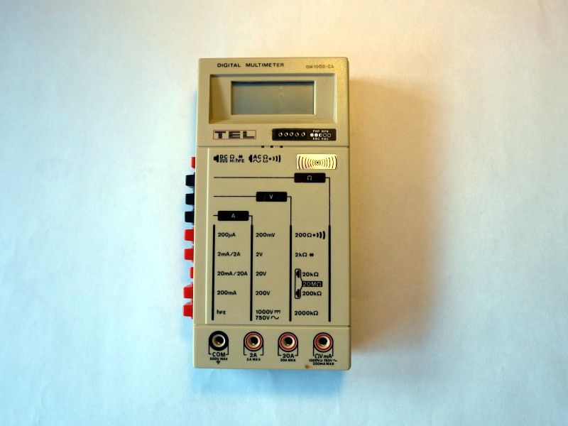
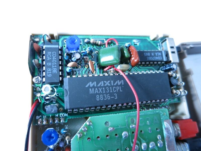
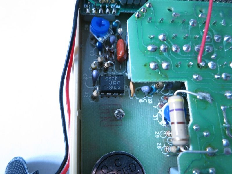
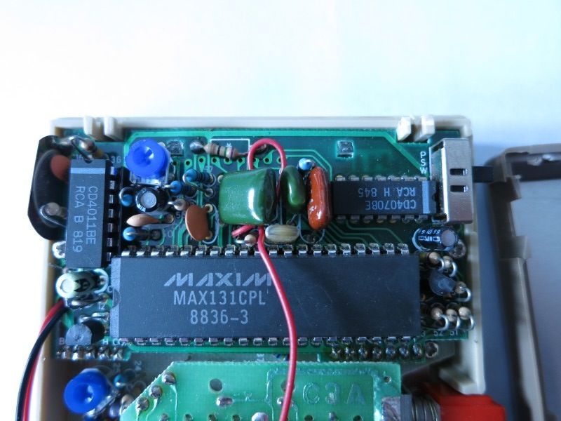
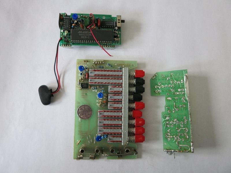
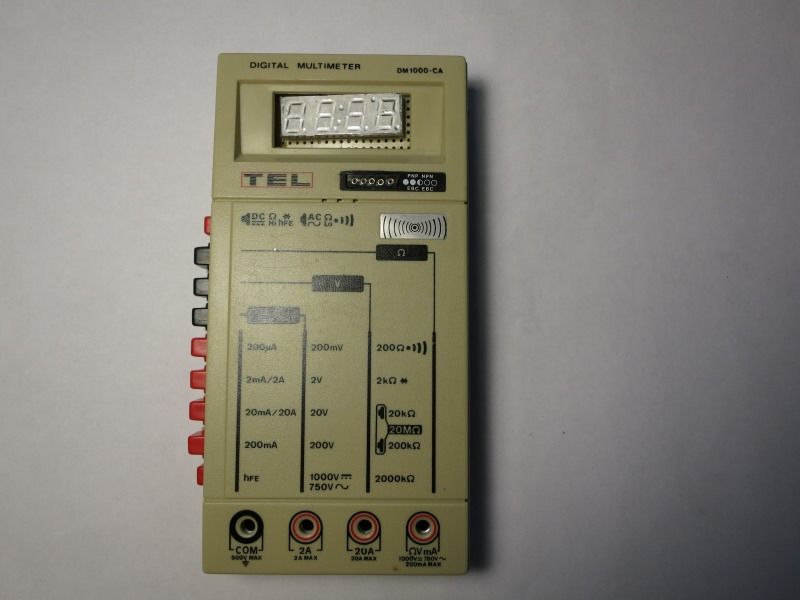
The project really kicked off when I was cleaning out some boxes of old stuff, and found the first digital multimeter I ever bought, probably around 1985 or so. It is a total piece of junk, was probably the same back then, but still expensive at the time. Interestingly enough, the main ADC chip of the DMM was a MAX131CPL – which is still available for purchase today!!
Off to work then.
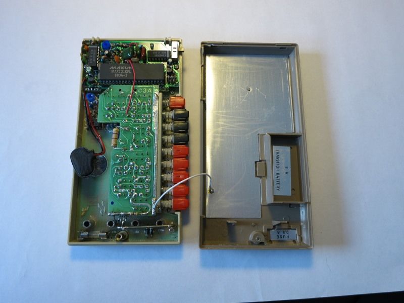
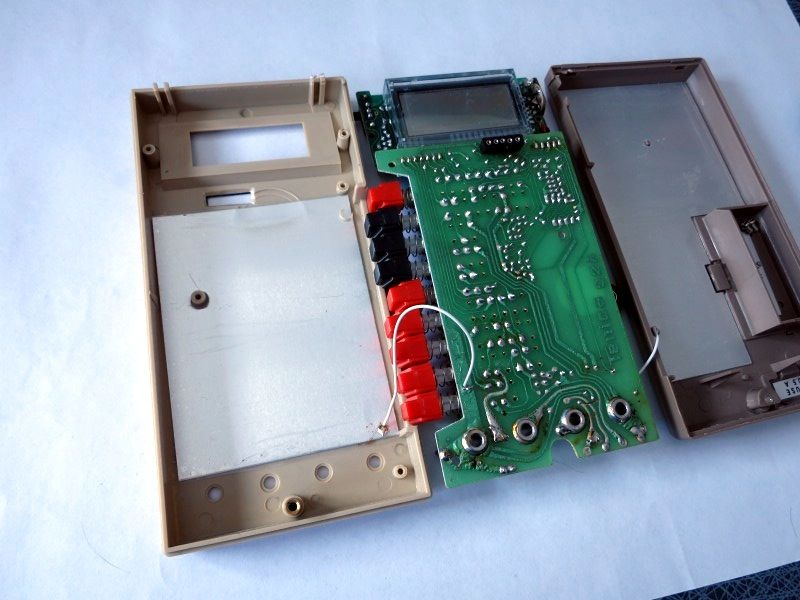
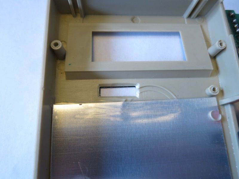
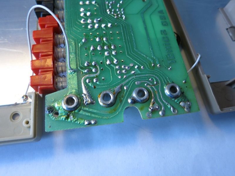
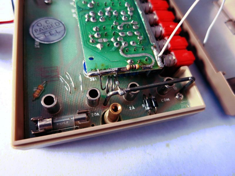
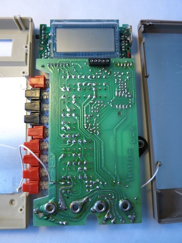
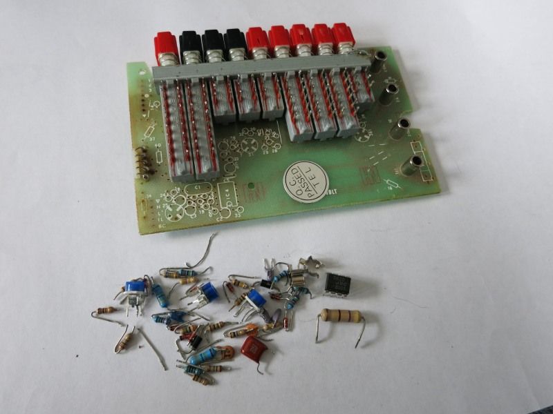
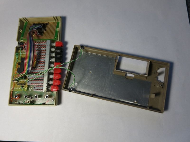
After ripping apart the DMM and stripping away all components, LCD, daughter boards etc (all through-hole components, of course. This is pre-SMD times.) I was left with some space in the DMM that should nicely handle the Superprobe circuitry. It might even be possible to squeeze a Dangerous Prototypes Part Ninja in there, and then multiplex the display between the two tools… Nah, one thing at a time, I’d rather finish the probe first.
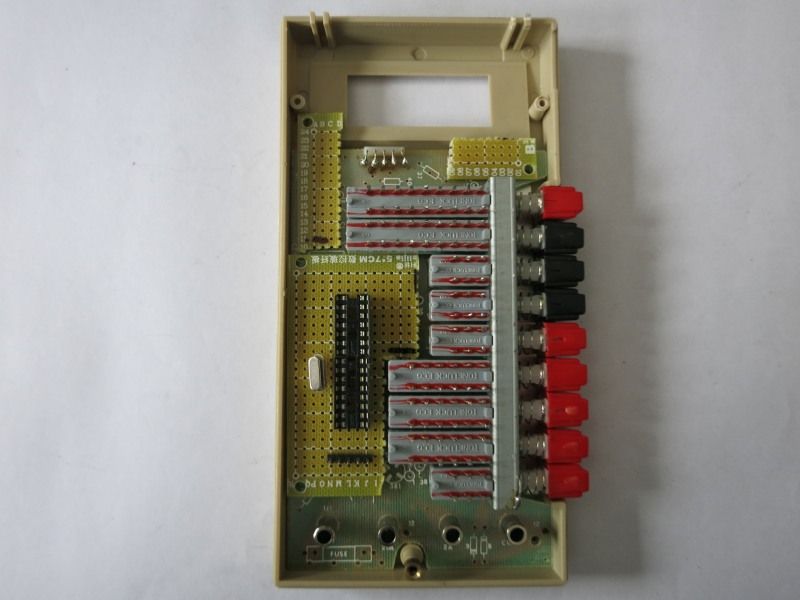
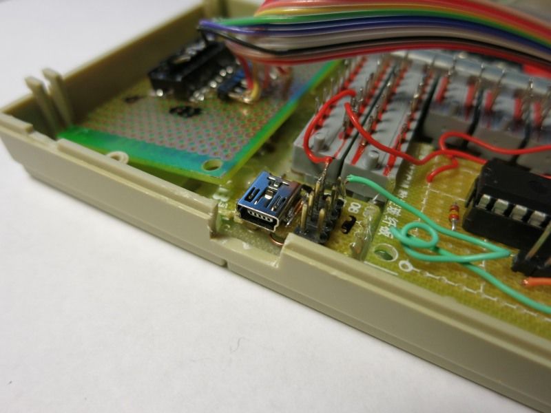
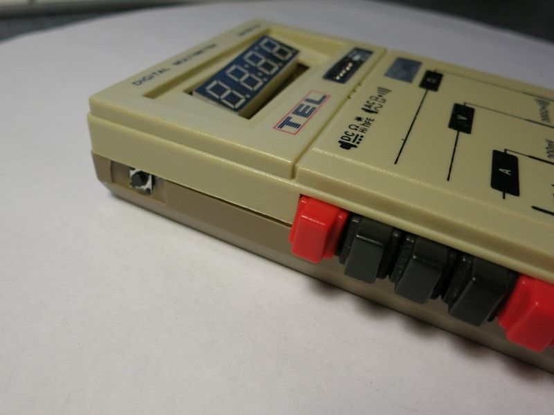
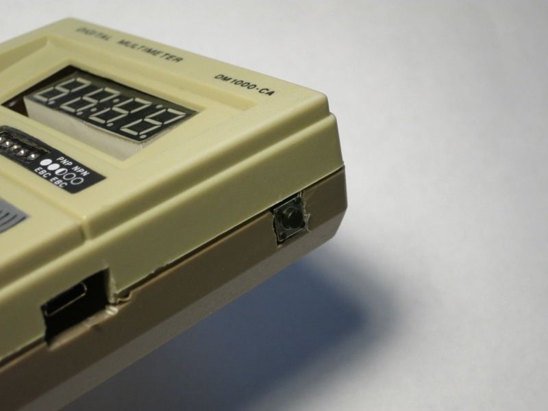
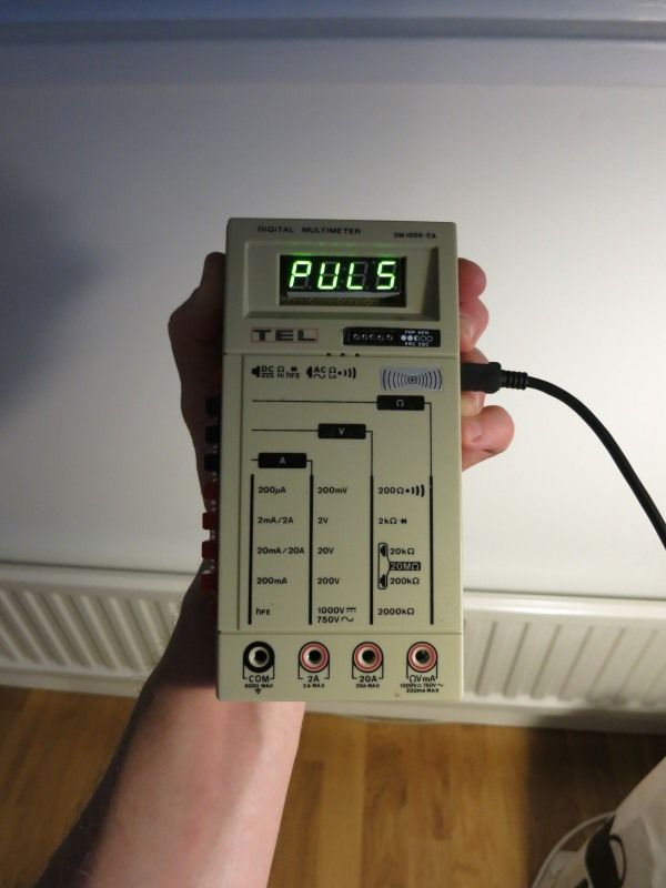
It all comes together quite nicely, with a mini USB jack providing power to the probe, the probe’s two push buttons are hot glued to the upper left/right sides of the case, making it easy to operate them both when the meter is on a table, and when it’s held in hand (in that caseit’s actually possible to operate the whole probe with a single hand, using thumb and index finger, while the probe rests in the palm. Nice!).
The input jacks from the original DMM are re-used and soldered to the input and Gnd of the probe, with one of the original mechanical range switches wired as on/off for the probe.
Works like a charm, the pictures below show the probe while in use.
Only one small glitch, not sure what’s going on. When the probe is turned off, it needs a minute or two before it agrees to turn on again. Some capacitor that need time to discharge, I guess. Thinking about adding a reset button.. should be an easy thing to add, just hooking pin 1 to ground through a small push button.
All in all – nice little project that is likely to be quite useful up ahead.